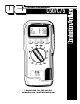
INSTRUCTION MANUAL C50/C75 1-800-547-5740 • Fax: (503) 643-6322 www.ueitest.com • email: info@ueitest.
Introduction The C50/C75 enables HVAC professionals to accurately test and service all residential combustion appliances. The extra large backlit LCD displays tw o parameters at one time. Easily choose the desired combustion parameter with the rotary selector. The optional printer allows you to print your readings to document your test results.
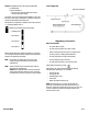
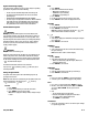
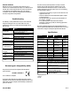
CO/CO2: The CO/CO2 ratio is the ratio of measured CO divided by calculated CO2. Probe Configuration It gives an indication of: • How good a gas sample the instrument is reading • How clean the boiler is running For example: A new or clean domestic boiler will display a ratio of less than 0.004, a unit in need of cleaning 0.004 - 0.008 and a unit in need of major overhaul will show greater than 0.008. This only shows a reading when a combustion test is being carried out.
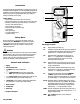
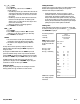
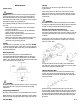
Analyzer Connections Flue (Tf) temperature socket Mains adapter socket Flue gas inlet Setting Inlet Temperature During the automatic calibration sequence the burner INLET (Ti) temperature used in the NET temperature calculation is stored in the analyzer. There are two methods of storing the INLET temperature. A. Without the flue probe connected temperature inside the analyzer is used (ambient temperature). B. If the flue probe is connected the temperature of the probe tip is used.
Regular Checks During Sampling Care must be taken at all times not to exceed the analyzer’s operating specifications.
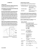
N G Cond 1. Press “ENTER”. 2. Select “N” for Net, or “G” for Gross or “COND” to calculate efficiency. • Gross Efficiency uses the gross calorific value of the fuel and deems that the latent heat of vaporization is lost up the flue of the appliance and is taken as a loss.
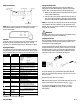
Combustion Combustion Theory In its simplest form, combustion is the combining of oxygen (O2) from the air with hydrogen (H) and carbon (C) from the fuel to form carbon dioxide (CO2), water (H2O) and energy (light and heat). Perfect combustion occurs when all of the carbon and hydrogen in the fuel unite with all of the oxygen supplied by the air. This is also referred to as “STOICHIOMETRIC Combustion”. In the real world perfect combustion is nearly impossible to achieve.
Net efficiency % = 100 - dry flue gas losses = 100 - 20.9 x K1n x (Tnet)/K2 x (20.9 - O2m) Gross efficiency % = 100 - {dry flue gas losses + wet losses} = 100 - {[20.9 x K1g x (Tnet)/K2 x (20.9 - O2m)] + [K3 x (1 + 0.001 x Tnett)]} Excess Air = [20.9/(20.9 - O2m) - 1] x 100 CO2% = [(20.9 - O2m) x K2/20.
Maintenance Periodic Service WARNING! Repair and service of this instrument is to be performed by qualified personnel only. Improper repair or service could result in physical degradation of the instrument. This could alter the protection from personal injury this meter provides to the operator. Perform only those maintenance tasks that you are qualified to do.
Annual Re-Calibration While the sensor has an expected life of more than two years in normal use it is recommended that the analyzer is re-calibrated at least annually, This is so that long-term drift on the sensor and electronics can be eliminated. local regulations may require more frequent re-calibration and users should check with appropriate authorities to ensure the comply with relevant guidelines.
C50/C75 Combustion Analyzer Limited Warranty The C50/C75 is warranted to be free from defects in materials and workmanship for a period of three years (two years on sensors) from the date of purchase. If within the warra n ty period your instrument should become inoperative from such defects, the unit will be repaired or replaced at UEi’s option.