
Install Instructions

4
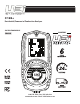
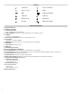
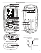
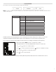
ANALYZER OVERVIEW
A. Infrared Printer Port
B. On/ Off (Power) Button
C. 6 Line Backlit Display
• Press any button to turn Back light on.
D. Pump Toggle Button: short press is data hold, long press turns pump on and off
E. UP Button
• Short press to navigate “UP”
F. Wireless/Store/Print Button: short press print, long press store
G. Down Button:
• Short press to navigate “DOWN”
H. ENTER Button: short press works as enter, long press turns on work light
I. Rotary Dial
J. Particle Filter (inside water trap)
K. Water Trap
L. LED Water Trap Indication
M. Protective Rubber Boot with Magnets
N. Serial Number QR Code: (Serial Number viewable under Protective Boot)
O. Sensors Fitted: (label under Protective Boot) Sensors that can be fitted in unit when shipped (CO-H2, CO, CO2, NO, O2)
P. Battery Compartment: (under Protective Boot)
Q. Grip Indentation: Indentation for fingers to grip analyzer
R. Water Trap Drain Plug (Red plug; take caution NOT to damage plug when removing protective boot)
S. Battery Charge USB Adapter Connection
T. Temperature Connections
• Flue Probe Temperature: T1
• Inlet Temperature: T2
U. Flue Gas Inlet Connection
V. Pressure Connections
• Pressure: P1
• Differential Pressure: P2
W. Infrared Printer Port
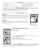
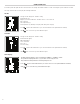
SYMBOLS
Low Battery Degrees Fahrenheit
Degrees Celsius Menu
LINK
LINK Pump Off & Pump On
Pump Start Pump Stop
Navigate Down Navigate Up
Enter Key Wireless/Store/Print