
Install Instructions


13
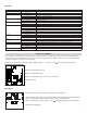
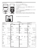
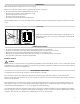
TEMPERATURE TESTING
Select the Temperature Rotary Dial position.
STATUS
FLUE 1
AUX
FLUE 2
TEMP
C
o
m
b
u
s
t
i
o
n
A
n
a
l
y
z
e
r
C161
C
O
C
O
2
T
E
M
P
Use the T1 connection for the Flue Probe temperature sensor
Use the T2 connection for the Inlet temperature sensor
Real time temperature difference
Real time pressure reading (pressure will only show is fitted)
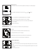
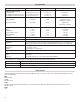
PRESSURE TESTING (IF PRESSURE FITTED)
WARNING
Never attempt to take a pressure reading without knowing the maximum pressure that might be present.
This instrument’s pressure transducer is rated at 2.3in H20 with a maximum pressure over range of 11.8in H20.
Using the black connectors and the manometer hose. Connect P1 for a single pressure or P1 and P2 for differential pressure.
STATUS
FLUE 1
AUX
FLUE 2
TEMP
C
o
m
b
u
s
t
i
o
n
A
n
a
l
y
z
e
r
C161
C
O
C
O
2
T
E
M
P
Use the T1 connection for the Flue Probe temperature sensor
Use the T2 connection for the Inlet temperature sensor
Real time temperature difference
Real time pressure reading (pressure will only show is fitted)
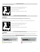
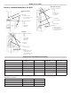
PRESSURE MEASUREMENT GOOD PRACTICE
WARNING
Before using the analyzer to measure the pressure of a gas/air ratio valve, read the boiler manufacturer’s manual thoroughly. If in
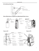
LARGE BORE TUBING ISSUES
If using larger bore tubing when performing pressure tests:
Push tubing over the rim of the This may not produce a gas tight seal.
spigot to ensure a gas tight seal.