C162/C163/C164 Flue Gas Combustion Analyzer with Heat Exchanger Test INSTRUCTION MANUAL Ex Te ch st FLUE 2 E1 FLU AU Temp Prs ENGLISH X O2 TE MP PRS STA TUS C163 Com busti o n A n al CO yze C r 1-800-547-5740 • Fax: (503) 643-6322 www.ueitest.com • Email: info@ueitest.
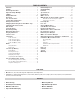
TABLE OF CONTENTS Functions. . . . . . . . . . . . . . . . . . . . . . . . . . . . . . . . . . . . . . . . . . . . . 2 Features. . . . . . . . . . . . . . . . . . . . . . . . . . . . . . . . . . . . . . . . . . . . . . 2 General Specifications . . . . . . . . . . . . . . . . . . . . . . . . . . . . . . . . 3 Important Safety Warnings . . . . . . . . . . . . . . . . . . . .
GENERAL SPECIFICATIONS • Operating Temperature: 0˚ to 113˚F (-18˚ to 45˚C) • Calibration: Recommended Annually • Storage Temperature: 0˚ to 113˚F (-18˚ to 45˚C) • Certification: CE Conformity, RoHS, REACH Compliant, AHRI 1260 standard • Operating Humidity: 15% to 90% R.H. • Back light: Yes • Dimensions: 8.54 x 4.18 x 1.86 inch • Battery Type: NiMH (AA) 3 • Accuracy: ± (% of reading + # of least significant digits) • Item Weight: 1.
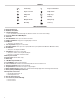
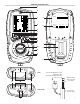
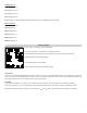
SYMBOLS Low battery Degrees Fahrenheit Degrees Celsius Pump Status Pump Start Pump Stop Hold Printing Navigate Down Navigate Up Enter Key Save Log ANALYZER OVERVIEW A. Infrared Printer Port B. On/ Off (Power) Button C. 6 Line Backlit Display • Press any button to turn Back light on (will turn off after 10 seconds of inactivity) D. Protective Rubber Boot With Magnets E. Status Bar F. Data Hold Button: Short press to hold current data G. Pump Toggle Button: Long press to toggle pump on and off H.
ANALYZER OVERVIEW (CONT.) A B C D Q R Serial No. Sensors CO Fitted: CO2 NO O2 E F G H Ex Te ch st Temp Prs FLUE 2 E1 FLU AU I J K L X STA TUS M S T TE MP PRS N O P O2 C163 Com busti o n An CO C er alyz U T2 T1 (C162) V W T2 P2 X T1 P1 Y (C163 & C164) Narrow Pin MUST be on the Right hand side.
OVERVIEW The direct measurement of CO2 is achieved using UEi’s own EOS technology sensor. CO2 is set to zero in fresh air automatically after the initial 60 second countdown. If “ZERO CO2” is indicated, ensure the unit is in outside fresh air before selecting the “Purge” option. It is very important that re-zeroing is done in outside fresh air as indoor CO2 levels are affected by human breath.
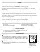
EMPTYING & CLEANING THE IN-LINE WATER TRAP • Remove the rubber plug • Allow the water to drain out • Re-insert the rubber plug CHANGING THE PARTICLE FILTER • • • • Remove the protective rubber boot Slide the water trap unit from the analyzer Remove the particle filter from its’ spigot and replace Slide the water trap back into position and replace the protective rubber boot QUICK START Turn on the analyzer by pressing the On/Off Button for 2 seconds until the unit activates.
DISPLAY PARAMETERS The large display is backlit with 6 lines, the last line is the Status Bar line. Menu Screen Time (settable parameter; HH:MM:SS, displayed in 24 hour clock format) Date (settable parameter; DD:MM:YY) Header (settable parameter; 16 character, 2 line; 10 characters can be added to Line 1 of the header, 6 characters to Line 2) IR Print (KMIRP2 or IRP-2) ˚C/˚F (settable parameter) NOx Ref (settable parameter; select 0.0% to 20.
Temp/Prs Screen Default Selections Are: T1 (displayed in F or C) T2 (displayed in F or C) ∆T (displayed in F or C) P (displayed in unit selected; mBar, InH20, hPa, mmHg, PSI, kPa, Pa, mmH20) (C163 & C164 only) Exch Test Screen Default Selections Are: O2 (displayed in %) COn (displayed in p) CO2 (displayed in %) NOn (displayed in p) NOxn (displayed in p) STATUS SCREEN Select “Status” on the dial to view the following: Current fuel selection. Use status bar to change fuel selection.
STATUS BAR Status Bar Icons The icons are designed to provide quick and simple instrument status information without having to navigate complicated menu systems or detract from the job at hand. Status Bar Icon Layout Pump Pump on Pump Pump paused Indicates data is being transmitted to either the App or the Printer Sending Data Battery Battery Status indication Status Bar Menu Options The Status Bar will offer the user Menu items based on the Selector Dial setting.
Menu Items MENU Time Date Header Sub Menu HH:MM:SS DD/MM/YY LINE 1 LINE 2 EXIT KMIRP IRP-2 ˚C ˚F ppm ppm(n) mg/m3 mg/m3(n) mg/kWh mg/kWh(n) English Espanaol Francais Gross Nett IR Print Temperature Scale Gas Unit Language Efficiency O2 ref Logs OPTIONS/COMMENTS 24 Hour Format (e.g. 7AM = 0:00:00, 7PM = 19:00:00) Customer info displays on print outs Customer info displays on print outs Select to print to KMIRP Select to print to IRP-2 Select ˚F or ˚C. Used for "Normalized" readings.
Viewing Stored Logs Once the view has been selected from the Logs Menu the following screen will be displayed: List of available Logs (Navigation and selection via the , and buttons). Log View Menu Options View stored Combustion Logs (Option will appear if Logs are available). View stored Auxiliary Logs (Option will appear if Logs are available). P TEM FLUE 2 E1 FLU AU Number of stored Temperature Logs and “Pressure if fitted” (Option will appear if Logs are available).
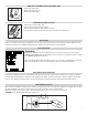
TEMPERATURE TESTING Select the Temperature Rotary Dial position. Use the T1 connection for the Flue Probe temperature sensor Use the T2 connection for the Inlet temperature sensor Real time temperature difference Real time pressure reading (pressure will only show is fitted) PRESSURE TESTING (IF PRESSURE FITTED) WARNING FLUE 2 FLU P Never attempt to take a pressure reading without knowing the maximum pressure that might be present. This instrument’s pressure transducer is rated at 2.
HEAT EXCHANGER TEST NOTE: Test results; O2, CO and Excess Air will show on the printout. There are many methods to test heat exchanger integrity. One of these is to observe the Excess Air, O2 and CO readings both before and after the blower turns on. If the heat exchanger is sealed your O2 and CO readings should remain fairly stable. A breach in the heat exchanger may allow fresh air to be forced into the flue after the blower turns on due to a pressure increase in the plenum.
PRINTER SELECTION Selecting a Printer Rotate selector Dial to Menu Position. Use or buttons to scroll to IR PRINT. Press button. Use or buttons to select either IRP-2 or KMIRP (KMIRP2 printer). Press button to save selection. Printing To print, simply press and release the PRINT BUTTON. Printing can be aborted by pressing the PRINT BUTTON again.
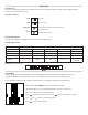
SPECIFICATIONS Parameter Range Resolution Accuracy Temperature Measurement Flue Temperature Inlet Temperature (Internal Sensor) Inlet Temperature (External Sensor) 32˚ to 1112˚F (0˚ to 600˚) 32˚ to 122˚F (0° to 50°C) 32˚ to 1112˚F (0˚ to 600˚) 0.1˚F (0.1˚C) 0.1˚F (0.1˚C) 0.1˚F (0.1˚C) ±0.5˚F (0.5˚C) ±1˚F (1˚C) ±0.5˚F (0.
WHERE TO TEST Air Conditioning / Heat Pump Suction Line: • Temperature Verify proper: • Static Duct Pressures • Temperature Differential • Static Pressure Drop Across Coils to condensing unit Boiler & Water Heaters & High Efficiency Modulating Hot Water Systems Boiler Verify proper combustion: • O2 • CO2 • CO Air Free • Stack Temp • Stack Draft Water Heater Draft Verify proper combustion: • O2 • CO2 • CO • Stack Temp • Efficiency HE Boiler Instant Water Heaters Draft Verify proper combustion: • O2 • CO
WHERE TO TEST (CONT.
POWERING OFF When you power off the analyzer, there is a 10 second purge. Make sure you do not exceed the analyzer’s operating specifications.
REPLACING THE BATTERIES This meter has been designed for use with both Alkaline or rechargeable Nickel Metal Hydride (NiMH) batteries. No other types are recommended and will void warranty. The analyzer is supplied with 3 (AA) size NiMH rechargeable batteries. These should be installed into the instrument. CAUTION Take great care when installing the batteries to observe correct polarity. Always check the meter for operation immediately after installing new batteries.
RECERTIFICATION SERVICES Turnaround Before starting any service work, we stabilize your analyzer in ambient air. Our standard turnaround is 2 working days for standard pre-paid recertification. If your unit requires extensive diagnostic or repair work, we will contact you with a quotation and estimated repair time prior to starting work. Pre-authorizing payment for your repair on a credit card saves time.
OTHER IMPORTANT FACTORS RELATING TO COMBUSTION The three T’s of combustion • Time: Amount of time that the fuel and oxygen are together in the combustion chamber • Temperature: How high the temperature is determines the rate of oxidation, or spread of combustion • Turbulence: How well the fuel and air are mixed These three factors are all interrelated and will move your results along the combustion curves. COMBUSTION MEASUREMENT TERMS Other parameters measured include Net temperature, draft and efficiency.
DISPOSAL Caution: This symbol indicates that equipment and its accessories shall be subject to separate collection and correct disposal. CLEANING: Periodically clean your meters’ case using a damp cloth. DO NOT use abrasive, flammable liquids, cleaning solvents, or strong detergents as they may damage the finish, impair safety, or affect the reliability of the structural components. STORAGE: Remove the batteries when instrument is not in use for a prolonged period of time.