Owners Manual
OWNERS MANUAL & MAINTENANCE Safety Notes Before using this meter, read all safety information carefully. In this manual the word “WARNING” is used to indicate conditions or actions that may pose physical hazards to the user. The word “CAUTION” is used to indicate conditions or actions that may damage this instrument. WARNING! This analyzer extracts combustion gases that may be toxic in relatively low concentrations. These gases are exhausted from the back of the instrument.
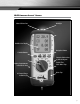
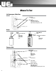
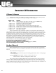
EAGLE Combustion Analyzer™ Overview Infrared Printer Port Worklight Backlit 4 Line Display Navigation Buttons Function Buttons Protective Rubber Boot w/ built-in Magnets Battery Compartments in back under boot AC Power/Charge Indicator Light Particle Filter Inside Water Trap Water Trap 3
General Maintenance • Calibrate your instrument annually to ensure it meets original performance specifications • Keep your instrument dry. If it gets wet, wipe dry immediately. Liquids can degrade electronic circuits • Whenever practical, keep the instrument away from dust and dirt that can cause premature wear • Although your instrument is built to withstand the rigors of daily use, it can be damaged by severe impacts.
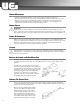
Batteries Replacement This meter has been designed for use with both alkaline and rechargeable Nickel Metal Hydride (NiMH) batteries. No other types are recommended. The analyzer is supplied with 4 “AA” size alkaline batteries. These should be installed into the instrument as shown in the diagram to the right and indicated on the back of the unit.
WHY TEST WITH EAGLE COMBUSTION ANALYZERS™ Verify Proper Operation Of Combustion Equipment • To verify that equipment is operating as the manufacture designed it to work.
WHAT RESULTS ARE GENERALLY ACCEPTABLE Atmospheric Gas Fired Burners • • • • Oxygen ............................................................................. 7 to 9% O2 Stack Temperature ......................................................... 325 to 500°F Draft (Water Column Inches)........................................... -.02 to -.04wc” Carbon Monoxide (parts per million) ............................. <100ppm Gas Fired Power Burners • • • • • Oxygen ..............................................
WHERE TO TEST Air Conditioning / Heat Pump Suction Line: • Temperature Verify proper: • Static Duct Pressures • Temperature Differential • Static Pressure Drop Across Coils to condensing unit Boiler & Water Heaters Water Heater Draft Boiler Verify proper combustion: • O2 • CO Air Free • Stack Temp • Stack Draft • SSE Verify proper combustion: • O2 • CO • Stack Temp • Efficiency Furnaces: 80% 80% Furnace Verify proper combustion: • O2 • CO • Stack Temp • Vent Pressure • Efficiency Set Up • Gas Pressure
Furnaces (continued): Atmospheric, Gas & Oil Atmospheric Furnace Draft Verify proper • Temperature Rise • AC side Static Pressure Drop across coils Verify proper combustion: • O2 • CO • Stack Temp • Efficiency Gas Furnace Verify proper combustion: • O2 • CO • Stack Temp • Vent Pressure • Efficiency Test • Limit Switch • Pressure Switch Set Up • Gas Pressure Verify proper: • Static Duct Pressure • Temperature Rise • AC side Static Pressure Drop across coils Oil Furnace Verify proper combustion: • O2 • CO
IMPORTANT CO INFORMATION CO Numbers To Remember Although there are several sources causing CO over-exposure conditions, there are a few common problems related to combustion, such as inadequate ventilation, tight buildings, and fuels releasing CO.
Residential Sources of CO 1. Chimney 2. Space Heaters 3. Vehicle exhaust 4. Water Heater 5. Furnace 6. Improperly vented appliances 7. Tobacco products 8. Fireplace (Gas or wood burning) 9. & 10. Gas appliances 1. 2. 3. 4. 5. 6. 7. 8. 9. 10. Stack Effect & Negative Pressure Stack Effect When air escapes through openings in the upper part of a building and is replaced with outside air entering through vents or cracks lower down.
COMBUSTION BASICS Introduction UEi combustion analyzers provide real time data that provides information on the condition of the combustion process of your equipment. This information is needed for proper setup and maintenance to verify proper operation. Benefits of combustion analysis are to increase efficiency thus reducing fuel costs, verification of proper combustion to reduce future problems, and to check for safe operation.
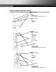
Near Ideal Combustion When we burn pure hydrogen in the air. Our atmosphere is 20.9% oxygen with the remaining 79.1% nitrogen. This is nearly as desirable as the example for ideal combustion with the only added loss being the heat that is carried away from your target with the nitrogen. Because nitrogen isn’t part of the combustion process, it enters the combustion chamber at the inlet temperature and leaves with some of the heat created by the combustion.
Perfect Combustion The term perfect combustion is also called stoichiometric combustion. This is the point where all of the fuel is burned with all the oxygen, leaving no undesirable byproducts. At this point all of the hydrogen in the fuel (H2) would combine with oxygen to form H2O, all of the carbon (C) would combine to form CO2, and all of the sulfur (S) would form SO2. There would be no additional air to carry heat away from the fire, and no undesirable byproducts would be created.
Other Important Factors Relating To Combustion • The three T’s of combustion – Time • Amount of time that the fuel and oxygen are together in the combustion chamber – Temperature • How high the temperature is determines the rate of oxidation, or speed of the combustion – Turbulence • How well the fuel and air are mixed • These three factors are all interrelated, and will move your results along the combustion curves.
Combustion Efficiency Calculations This identifies three sources of loss associated with fuel burning: • Losses due to flue gasses: - Dry Flue gas loss, Moisture and hydrogen, - Sensible heat of water vapor, Unburned gas • Losses due to refuse: - Combustible in ash, riddling and dust • Other losses: - Radiation, convection, conduction other unmeasured losses Net efficiency calculations assume that the energy contained in the water vapor (formed as a product of combustion and from wet fuel) is recove
Information on Excess Air • Excess Air - Theoretically perfect combustion would have the exact amount of O2 to combine with all of the fuel, resulting in no excess air.
GLOSSARY Display Parameters On UEi Combustion Analyzers • TF (Flue Temperature) Used to calculate net temperature in Fahrenheit or Centigrade. Will show ambient temperature after fresh air calibration and ‘- O C - ’ if the flue probe is disconnected.
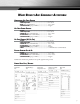
EAGLE SPECIFICATIONS Features C75 Worklight Low battery indicator Individual print-out reports Rotary selector 4 Memory positions (various tests) 20 Infrared printer port 4 Backlit display 2 Lines Boot with integral magnet 4 User programmable headers 4 Time & date stamp 4 Temp Measurement Flue Temp Range (T1 C125/C127) Inlet Temp Range:Probe (T2 C125/C127) Inlet Temp Range: Ambient Net Temp (∆T)** Resolution Flue (T1, Inlet T2, & Net ∆T) Accuracy Inlet Temp Ambient Accuracy Gas Measurement Oxygen O2 R
EAGLE Combustion Analyzers™ Limited Warranty The Eagle Combustion Analyzers (C75/C125/C127) is warranted to be free from defects in materials and workmanship for a period of three years (two years on sensors) from the date of purchase. If within the warranty period your instrument should become inoperative from such defects, the unit will be repaired or replaced at UEi’s option.