
User's Manual


Digital ATSC Exciter-Modulator System Chapter 2,
Installation and Operating Instructions
Axcera Axciter, Rev. 0 31
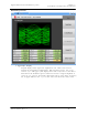
DTVision Non-Linear - Optional
This section contains information regarding the DTVision Screens. These screens are
optional diagnostic screens. They are not necessary for the operation of the Axciter.
However, they greatly enhance the experience. These graphs provide the same type of
views as an EFA.
All of the Nonlinear screens have the following reference values displayed
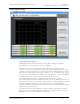
EVM
The error vector magnitude (EVM) value indicates quality of the digital
modulation. EVM is defined as the RMS error at the sampling instants divided
by the RMS of the ideal symbols. The error is expressed as a percentage. As
signal quality increases, this value decreases.
S/N
The transmitted signal quality is also expressed as an in-band signal to noise
ratio, expressed in dB. As signal quality increases, this value will increase
(logarithmically).
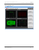
DAC Headroom
ever negative, then there is clipping in the IF modulator, nonlinear equalizer,
and/or the DAC. If this happens, lower the unity gain reference point for the
nonlinear equalizer.
EVM
The error vector magnitude (EVM) value indicates quality of the digital
modulation. EVM is defined as the RMS error at the sampling instants divided
by the RMS of the ideal symbols. The error is expressed as a percentage. As
signal quality increases, this value decreases.
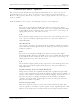
S/N
The transmitted signal quality is also expressed as an in-band signal to noise
ratio, expressed in dB. As signal quality increases, this value will increase
(logarithmically).
Digital to Analog Converter (DAC) Headroom
This parameter shows the amplitude (in dB) of the equalized IF signal with
respect to the maximum output from the digital to analog converter (DAC). A
positive value indicates normal operation and no clipping. If this value is ever
negative, then there is clipping occurring in the IF modulator, nonlinear
equalizer, and/or the DAC. If this happens, lower the unity gain reference
point for the nonlinear equalizer.
Peak to Average Ratio
This value shows the peak to average ratio of the transmitted signal. This
value is typically 6 to 8 dB for a perfect signal. A value significantly lower will
indicate peak compression. A small amount of peak compression is normal.