
User's Manual


Innovator CU0TD-1/CU0RD-1 – CU4TD/CU4RD ATSC System Set-up
Transmitter/Regenerative Translator Procedure
Instruction Manual, Rev. 2 123
20. Verify that the VSWR Cutback LED, DS6, comes on and the Reflected Power
drops to approximately 6%.
21. Reconnect the RF output connector and increase the power back up to 100%
using R75.
This completes the set up of the ALC board and the Forward and Reflected Power
Calibration.
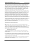
Figure 63: (A4) Output Detector Board (1312207)
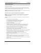
Figure 64: (A5) ALC Board (1315006)
R23
FORWARD
CAL ADJ
R7
REFLECTED
CAL ADJ
R38
OVERDRIVE
THRESHOLD
S1
AUTO/MAN
R75
ALC ADJ
R62
MAN ADJ
J4