
User's Manual


Innovator CU0TD-1/CU0RD-1 – CU4TD/CU4RD ATSC Board Descriptions
Transmitter/Regenerative Translator
Instruction Manual, Rev. 2 116
(A9 & A10) Power Supplies used in CX Exciter/Driver
MODEL (A10) POWER SUPPLY VOLTAGE AC INPUT VOLTAGE
CU0TD/RD-1 +48VDC 115VAC or 230VAC
CU0TD/RD-2 +28VDC 115VAC or 230VAC
CU0TD/RD-3 +48VDC 115VAC or 230VAC
CU0TD/RD-4 +42VDC w/878A or +48VDC w/888A 230VAC
CU0TD/RD-5 +42VDC w/878A or +48VDC w/888A 230VAC
Table 38: Model Number with corresponding (A10) Voltages and AC Input
Voltages
Voltages for the operation of the boards in the drawer are generated by (A9) a +5VDC
and ±12VDC power supply and (A10) a switching power supply which is a different
power supply providing a different voltage in each model. See the chart above. The
115VAC or 230VAC input to the CU0TD/RD-1 thru CU0TD/RD-3 drawer connects through
the AC power cord at J6, the power entry module located on the rear panel of the
drawer.
The CU0TD/RD-4 & CU0TD/RD-5 drawer only operates with 230VAC. An On/Off
10A/250VAC circuit breaker is part of the power entry module. With the circuit breaker
switched On, the (L) line input is wired to F1 a 10 Amp fuse for over current protection.
The AC lines are connected to terminal block TB1, which distributes the AC to (A9 and
A10) the two DC power supplies. There are two varistors, mounted on TB1, connected
from the line input to neutral and to ground for surge protection. The AC in the
CU0TD/RD-4 & CU0TD/RD-5 also connects to the (A11) fan mounted on the rear panel
of the drawer. The fan will run when AC is applied to the drawer and the circuit breaker
is switched On. The +5VDC and ±12VDC outputs of the (A9) power supply connects to
the terminal block (TB2) that distributes the DC to the boards in the drawer. Some of
the +5VDC and ±12VDC outputs connect directly to the 8 VSB Demodulator and 8 VSB
Modulator
The +28/+42/+48VDC outputs of the (A10) power supply connect to the (A8) CX
Control Board, which then supplies the switched +28/+42/+48VDC VDC to the (A6)
Amplifier Assembly. In CU0TD/RD-1 thru CU0TD/RD-3 drawers the DC output of the
(A10) power supply also connects to the (A11) fan mounted on the rear panel, which will
operate when AC is applied to the drawer, the On/Off circuit breaker is On and the (A10)
power supply is operating.
Descriptions of Boards Used in External ATSC Amplifier Drawers
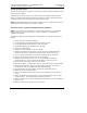
(A7) Amplifier Control Board (1315011 or 1312260)
Figure 62: Amplifier Control Board
The Amplifier Control Board is mounted in the top front facing the rear of the Amplifier
Drawer as shown above.
SW1