Instruction Manual Innovator, CU0TD-1/CU0RD-1, 5 Watt CU4TD/CU4RD, 2500 Watt UHF, ATSC Transmitter/ Regenerative Translator w/ Adaptive Modulator UBS-Axcera Inc. 103 Freedom Drive • P.O. Box 525 • Lawrence, PA 15055-0525, USA Phone: 724-873-8100 • Fax: 724-873-8105 www.UBS-Axcera.com • info@UBS-Axcera.
RESTRICTIONS ON USE, DUPLICATION OR DISCLOSURE OF PROPRIETARY INFORMATION This document contains information proprietary to UBS-Axcera, to its affiliates or to a third party to which UBS-Axcera may have a legal obligation to protect such information from unauthorized disclosure, use or duplication.
Innovator CU0TD-1/CU0RD-1 – CU4TD/CU4RD ATSC Transmitter/Regenerative Translator Table of Contents Table of Contents Introduction .........................................................................................................1 Manual Overview ...............................................................................................1 UBS-Axcera Numbering System Explanation..........................................................1 Assembly Designators ........................................
Innovator CU0TD-1/CU0RD-1 – CU4TD/CU4RD ATSC Transmitter/Regenerative Translator Table of Contents Windowing (Window Enabled) ........................................................................... 36 Internal Frequency Reference ............................................................................ 36 Manual Digital Linear and Non-linear Pre-correctors ............................................. 37 Adaptive Non-linear and Linear Digital Pre-correction .........................................
Innovator CU0TD-1/CU0RD-1 – CU4TD/CU4RD ATSC Transmitter/Regenerative Translator Table of Contents Display Alarms.......................................................................................... 73 Firmware Upgrade..................................................................................... 73 SNMP ............................................................................................................. 74 8VSB ATSC Parameters ...........................................................
Innovator CU0TD-1/CU0RD-1 – CU4TD/CU4RD ATSC Transmitter/Regenerative Translator Table of Contents (A6-A2) BLF881 Single Stage Amplifier Board (1314882) ............................. 114 (A6-A3) Dual BLF888A Pallet Assembly (1315347) ...................................... 114 (A7) Output Detector Board (1312207) ............................................................ 115 (A8) Control Card, Innovator CX (1312543) ......................................................
Innovator CU0TD-1/CU0RD-1 – CU4TD/CU4RD ATSC Transmitter/Regenerative Translator Introduction Introduction Manual Overview This manual contains the description of the Innovator CU0TD-1/CU0RD-1 – CU4TD/CU4RD Transmitter/Regenerative Translator and the circuit descriptions of the boards, which make up the system. The manual also describes the installation, setup and alignment procedures for the system.
Innovator CU0TD-1/CU0RD-1 – CU4TD/CU4RD ATSC Transmitter/Regenerative Translator Introduction Assembly Designators UBS-Axcera has assigned assembly numbers, Ax designations such as A1, where x=1,2,3…etc, to all assemblies, modules, and boards in the system. These designations are referenced in the text of this manual and shown on the block diagram and interconnect drawings provided in Appendix A.
Innovator CU0TD-1/CU0RD-1 – CU4TD/CU4RD ATSC Transmitter/Regenerative Translator Introduction Retain Manuals – The manuals for the system should be retained at the system site for future reference. UBS-Axcera provides two manuals for this purpose; one manual can be left at the office while the other can be kept at the site. Heed all Notes, Warnings, and Cautions – All of the notes, warnings, and cautions listed in this safety section and throughout the manual must be followed.
Innovator CU0TD-1/CU0RD-1 – CU4TD/CU4RD ATSC Transmitter/Regenerative Translator Introduction Return Material Procedure To insure the efficient handling of equipment or components that have been returned for repair, UBS-Axcera requests that each returned item be accompanied by a Return Material Authorization Number (RMA#). The RMA# can be obtained from any UBSAxcera Field Service Engineer by contacting the UBS-Axcera Field Service Department at 724-873-8100 or by Fax at 724-873-8105.
Innovator CU0TD-1/CU0RD-1 – CU4TD/CU4RD ATSC Transmitter/Regenerative Translator Introduction Limited One Year Warranty for UBS-Axcera Products UBS-Axcera warrants each new product that it has manufactured and sold against defects in material and workmanship under normal use and service for a period of one (1) year from the date of shipment from UBS-Axcera's plant, when operated in accordance with UBS-Axcera's operating instructions. This warranty shall not apply to tubes, fuses, batteries, bulbs or LEDs.
Innovator CU0TD-1/CU0RD-1 – CU4TD/CU4RD ATSC Transmitter/Regenerative Translator Introduction WARNING!!! HIGH VOLTAGE DO NOT ATTEMPT TO REPAIR OR TROUBLESHOOT THIS EQUIPMENT UNLESS YOU ARE FAMILIAR WITH ITS OPERATION AND EXPERIENCED IN SERVICING HIGH VOLTAGE EQUIPMENT. LETHAL VOLTAGES ARE PRESENT WHEN POWER IS APPLIED TO THIS SYSTEM. IF POSSIBLE, TURN OFF POWER BEFORE MAKING ADJUSTMENTS TO THE SYSTEM.
Innovator CU0TD-1/CU0RD-1 – CU4TD/CU4RD ATSC Transmitter/Regenerative Translator Introduction EMERGENCY FIRST AID INSTRUCTIONS Personnel engaged in the installation, operation, or maintenance of this equipment are urged to become familiar with the following rules both in theory and practice. It is the duty of all operating personnel to be prepared to give adequate Emergency First Aid and thereby prevent avoidable loss of life. RESCUE BREATHING 1. Find out if the person is breathing.
Innovator CU0TD-1/CU0RD-1 – CU4TD/CU4RD ATSC Transmitter/Regenerative Translator Introduction dBm, dBw, dBmV, dBµ µV, & VOLTAGE EXPRESSED IN WATTS 50 Ohm System WATTS 1,000,000,000,000 100,000,000,000 10,000,000,000 1,000,000,000 100,000,000 10,000,000 1,000,000 100,000 10,000 1,000 100 50 20 10 1 0.1 0.01 0.001 0.0001 0.00001 0.000001 0.0000001 0.00000001 0.000000001 0.0000000001 0.00000000001 0.
Innovator CU0TD-1/CU0RD-1 – CU4TD/CU4RD ATSC Transmitter/Regenerative Translator Introduction USEFUL CONVERSION FACTORS TO CONVERT FROM TO MULTIPLY BY mile (US statute) kilometer (km) inch (in) millimeter (mm) inch (in) centimeter (cm) inch (in) meter (m) foot (ft) meter (m) yard (yd) meter (m) mile per hour (mph) kilometer per hour(km/hr) mile per hour (mph) meter per second (m/s) pound (lb) kilogram (kg) gallon (gal) liter U.S. liquid (One U.S. gallon equals 0.
Innovator CU0TD-1/CU0RD-1 – CU4TD/CU4RD ATSC Transmitter/Regenerative Translator Instruction Manual, Rev.
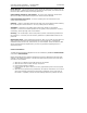
Innovator CU0TD-1/CU0RD-1 – CU4TD/CU4RD ATSC Transmitter/Regenerative Translator Introduction RETURN LOSS VS. VSWR 0 -10 -20 R E T U R N -30 dB L O S S -40 -50 -60 -70 1.001 1.01 1.1 VSWR Instruction Manual, Rev. 2 11 2.
Innovator CU0TD-1/CU0RD-1 – CU4TD/CU4RD ATSC Transmitter/Regenerative Translator Introduction ABBREVIATIONS/ACRONYMS AC: Alternating Current FEC: Forward Error Correction AFC: Automatic Frequency Control FM: Frequency Modulation FPGA: ALC: Automatic Level Control Field Programmable Gate Array AM: Amplitude Modulation Hz: Hertz AGC: Automatic Gain Control I/C: Interconnect ATSC: Advanced Television Systems Committee (Digital) ICPM: Incidental Carrier Phase Modulation AWG: American W
Innovator CU0TD-1/CU0RD-1 – CU4TD/CU4RD ATSC Transmitter/Regenerative Translator This page has intentionally been left blank. Instruction Manual, Rev.
Innovator CU0TD-1/CU0RD-1 – CU4TD/CU4RD ATSC Transmitter/Regenerative Translator System Description System Description Product Architecture The Innovator CX Series Systems can be configured as DTV Transmitters (i.e CU3TD) or Regenerative Translators (i.e CU3RD). The DTV Transmitter (TD) takes an ASI input and converts it to an On-Channel DTV RF output signal. The Regenerative Translator (RD) accepts an On-Channel RF signal (-79 to –8 dBm) and converts it to an On-Channel DTV RF output signal.
Innovator CU0TD-1/CU0RD-1 – CU4TD/CU4RD ATSC Transmitter/Regenerative Translator System Description When configured to operate as a Regenerative Translator (RD), the DTV ON Channel RF Input at (J1 or J5), (-8 to -79 dBm) connects to the Tuner Input Jack on (A1) the 8 VSB Demodulator Board (1308275) supplied with the (RD) kit. The 8 VSB Demodulator Board converts the DTV input to a SMPTE-310 output at (J13), which is connected to the input jack on the (A12) 8VSB Modulator Board.
Innovator CU0TD-1/CU0RD-1 – CU4TD/CU4RD ATSC Transmitter/Regenerative Translator System Description Amplifier Drawers The CU1TD/RD-1 ATSC system is made up of a CX driver drawer and a 250 Watt ATSC amplifier drawer. The driver drawer connects to the 250 Watt amplifier drawer and supplies the needed drive level to produce the 250 Watts output of the system. The control and operating parameters of the 250 Watt amplifier drawer are displayed on the LCD Screen on the driver drawer.
Innovator CU0TD-1/CU0RD-1 – CU4TD/CU4RD ATSC Transmitter/Regenerative Translator System Description The CU1TD/RD-3, 750 Watt ATSC system is made up of a CX driver drawer and a 750 Watt amplifier drawer. The output of the driver drawer connects to the amplifier drawer and supplies the needed drive level to produce the 750 Watts output of the system. The control and operating parameters of the amplifier drawer are displayed on the LCD Screen on the driver drawer.
Innovator CU0TD-1/CU0RD-1 – CU4TD/CU4RD ATSC Transmitter/Regenerative Translator System Description Pre-Filter Sample (Non-Linear Distortion) The pre-filter sample from the pre-filter coupler connects to (J3), the RF input 1 jack, located on the rear panel of the driver drawer. This sample connects to the modulator board where it is used in the correction system.
Innovator CU0TD-1/CU0RD-1 – CU4TD/CU4RD ATSC Transmitter/Regenerative Translator This page has intentionally been left blank. Instruction Manual, Rev.
Innovator CU0TD-1/CU0RD-1 – CU4TD/CU4RD ATSC Transmitter/Regenerative Translator Unpacking, Installation & Maintenance Unpacking, Installation and Maintenance Unpacking UBS-Axcera certifies that upon leaving our facility all equipment was undamaged and in proper working order. It is imperative that all packages be inspected immediately upon arrival to verify that no damage occurred in transit to the site.
Innovator CU0TD-1/CU0RD-1 – CU4TD/CU4RD ATSC Transmitter/Regenerative Translator Unpacking, Installation & Maintenance Installation The Innovator CX Series transmitters are designed for simple installation. Expensive test equipment is not required for installation and set up and to keep a system operational.
Innovator CU0TD-1/CU0RD-1 – CU4TD/CU4RD ATSC Transmitter/Regenerative Translator Unpacking, Installation & Maintenance Check that any additional equipment, which is included in the system that extends above or to the side of the mounting rack, has sufficient clearance space. Refer to the custom racking plan for the system, if prepared, for detailed information. Drawer Slide Installation If the system is pre-mounted in a cabinet skip this section.
Innovator CU0TD-1/CU0RD-1 – CU4TD/CU4RD ATSC Transmitter/Regenerative Translator Unpacking, Installation & Maintenance If your system contains an optional preamp check that the 24VDC power supply is connected to the preamp and an AC source. Multi Amplifier Drawer Systems If your system is a CU1TD/RD-1, CU1TD/RD-2 or CU1TD/RD-3, it also contains one amplifier drawer. In CU2TD/RD and higher power systems, multiple amplifier drawers are included.
Innovator CU0TD-1/CU0RD-1 – CU4TD/CU4RD ATSC Transmitter/Regenerative Translator Unpacking, Installation & Maintenance The AC distribution panel in a CU2TD has three circuit breakers that distribute the AC to the individual drawers, which are the Exciter and the two power amplifier drawers. The circuit breakers, which are accessed through the rear door of the cabinet, supply the AC though AC line cords, that connect to the AC input jacks mounted on the rear panels of the drawers.
Innovator CU0TD-1/CU0RD-1 – CU4TD/CU4RD ATSC Transmitter/Regenerative Translator Unpacking, Installation & Maintenance Figure 3: CX Exciter/Driver Rear Panel Port Type J1 BNC J2 BNC J3 BNC J4 BNC J5 BNC J6 BNC J7 J9 BNC N J10 IEC J11 9 Pos Male D J12 15 Pos Female D J13 RJ-45 J14 RJ-45 J15 Front Panel BNC J16 Front Panel 9 Pos Female D Function Input A: On Channel RF Input (RD) –78 to –8 dBm or ASI Input or SMPTE-310M Input Input B: ASI Input or SMPTE-310M Input Input C: RF S
Innovator CU0TD-1/CU0RD-1 – CU4TD/CU4RD ATSC Transmitter/Regenerative Translator Unpacking, Installation & Maintenance NOTES: 1) If your transmitter (TD) system contains an Optional ASI to S310 Converter, connect the ASI output of the STL to the ASI in jack on the rear panel of the converter.
Innovator CU0TD-1/CU0RD-1 – CU4TD/CU4RD ATSC Transmitter/Regenerative Translator Unpacking, Installation & Maintenance If used, connect the external forward power sample from the pre-filter coupler to the 50Ω BNC Input C jack (J3) located on the rear panel of the CX drawer. If used, connect the external forward power sample from the post-filter coupler to the 50Ω BNC Input D jack (J4) located on the rear panel of the CX drawer.
Innovator CU0TD-1/CU0RD-1 – CU4TD/CU4RD ATSC Transmitter/Regenerative Translator Unpacking, Installation & Maintenance Power Monitoring Connections to J11 In systems with one or more external amplifiers, J11 is used to communicate the output forward and reflected metering voltages back to the driver. J11 is connected directly to the external amplifier when there is only one external amplifier and is connected through the system metering module when multiple external amplifiers are used.
Innovator CU0TD-1/CU0RD-1 – CU4TD/CU4RD ATSC Transmitter/Regenerative Translator Remote Signal Name Pin Designation Power Raise J12-3 Power Lower J12-4 System Interlock J12-5 Set to Modulation Type (system specific and may not be available) J12-6 Set Channel (Set Up 1 or Set Up 2) - (system specific and may not be available) J12-7 Ground J12-8 System Forward Power Level J12-9 System Aural Power Level J12-10 System Reflected Power Level J12-11 Report Input Status J12-12 Report Fault Sta
Innovator CU0TD-1/CU0RD-1 – CU4TD/CU4RD ATSC Transmitter/Regenerative Translator Remote Signal Name Pin Designation Report Operate Status J12-14 Ground J12-15 Unpacking, Installation & Maintenance Signal Type Description Normally or has a Fault. Not available in dual exciter systems. (Low = OK : Floating = Fault) Discrete Open Collector Output. – Indicates whether system is in Operate or Standby. Not available in dual exciter systems. (Low = Operate : Floating = Standby) Ground.
Innovator CU0TD-1/CU0RD-1 – CU4TD/CU4RD ATSC Transmitter/Regenerative Translator Unpacking, Installation & Maintenance HPA Output Connections The amplifier drawer digital RF On-Channel output is at the (J12) 50Ω “7/16” (1.1cm) DIN RF output jack, located on the rear panel of the drawer. The RF output jack is connected to the low pass filter, digital mask filter, then to the antenna for your system in single amplifier systems.
Innovator CU0TD-1/CU0RD-1 – CU4TD/CU4RD ATSC Transmitter/Regenerative Translator Unpacking, Installation & Maintenance Maintenance The Innovator CX Transmitters are designed with components that require little or no periodic maintenance, except for the routine cleaning of air intakes, fans and module front panels as well as the periodic check of general tightness of hardware.
Innovator CU0TD-1/CU0RD-1 – CU4TD/CU4RD ATSC Transmitter/Regenerative Translator Unpacking, Installation & Maintenance This page has intentionally been left blank. Instruction Manual, Rev.
Innovator CU0TD-1/CU0RD-1 – CU4TD/CU4RD ATSC Transmitter/Regenerative Translator 8VSB ATSC Modulator 8VSB ATSC Modulator Board The Modulator design is based on the Advanced Universal Modulator board, customized to comply with ATSC standards A/53, A/54 A/64, A/110 and A/153. The modulator converts an MPEG-2 transport stream to an 8-VSB modulated RF signal.
Innovator CU0TD-1/CU0RD-1 – CU4TD/CU4RD ATSC Transmitter/Regenerative Translator 8VSB ATSC Modulator Web GUI The modulator hosts an internal web interface (Web GUI) accessible through its Ethernet port. The Web GUI is an intuitive interface allowing the user to access the current modulator status and configure the operational parameters of the system. The Web interface uses a simple hierarchical menu structure which provides access to all modulator parameters.
Innovator CU0TD-1/CU0RD-1 – CU4TD/CU4RD ATSC Transmitter/Regenerative Translator 8VSB ATSC Modulator Transport Stream Inputs DVB-ASI Inputs The DVB-ASI inputs accept an MPEG-2 transport stream according to DVB recommendations. Both 188 and 204 byte transport packets are supported. Automatic switching provides near seamless switching to a secondary transport stream if the primary transport steam source fails. SMPTE 310M Inputs The SMPTE 310M input accept a MPEG-2 transport stream.
Innovator CU0TD-1/CU0RD-1 – CU4TD/CU4RD ATSC Transmitter/Regenerative Translator 8VSB ATSC Modulator Manual Digital Linear and Non-linear Pre-correctors The modulator is equipped with digital linear and non-linear pre-correctors (predistorters) that can significantly improve the performance of a transmitter. The Precorrector function can be switched on and off from the Web GUI or CLI.
Innovator CU0TD-1/CU0RD-1 – CU4TD/CU4RD ATSC Transmitter/Regenerative Translator 8VSB ATSC Modulator The processor compares the captured data to the ideal waveform curves (stored on the capture card) and calculates NLP or LP coefficients. The coefficients are then transferred to the modulator board for control of the back-end Non-linear or Linear Digital Precorrector.
Innovator CU0TD-1/CU0RD-1 – CU4TD/CU4RD ATSC Transmitter/Regenerative Translator 8VSB ATSC Modulator Main Status Page Figure 6: Modulator Global Status Page (MFN Mode) The main (Global) status page provides general information about parameter settings and the modulator’s alarm status. The pull down menus, located at the top of the status page, provide links to other pages that control various parameters and alarm functions. Instruction Manual, Rev.
Innovator CU0TD-1/CU0RD-1 – CU4TD/CU4RD ATSC Transmitter/Regenerative Translator 8VSB ATSC Modulator GUI Navigation and Structure The main (Global) status page seen in Figure 6 demonstrates the hierarchical structure of the Web GUI interface. Along the top of the page are a row of five icons with drop down menus.
Innovator CU0TD-1/CU0RD-1 – CU4TD/CU4RD ATSC Transmitter/Regenerative Translator 8VSB ATSC Modulator Changing Parameters Before changes to system parameters are accepted the user must first click the submit button. The example below has the user clearing the alarm log in the Clear Log screen. Figure 7: Example of Submitting a Parameter Change Once the user has selected “Yes” for the Clear Log pull down box, the user will then need to click Submit.
Innovator CU0TD-1/CU0RD-1 – CU4TD/CU4RD ATSC Transmitter/Regenerative Translator 8VSB ATSC Modulator Global Status Page The Global status page appears upon login and provides general information about parameter settings and the modulator’s alarm status. The list of parameters will change dynamically as the transmission mode (MFN or SFN) is changed. See Figure 8 or Figure 9 for details.
Innovator CU0TD-1/CU0RD-1 – CU4TD/CU4RD ATSC Transmitter/Regenerative Translator 8VSB ATSC Modulator Figure 9: Modulator Global Status Page (SFN Mode) Instruction Manual, Rev.
Innovator CU0TD-1/CU0RD-1 – CU4TD/CU4RD ATSC Transmitter/Regenerative Translator 8VSB ATSC Modulator Config Menu The Config menu contains the following drop down items, as seen in Figure 10. • Modulator Mode • Transmission • Input • Output • RF Channels • Non-Linear Precorrector • Linear Precorrector • Site • UART Baudrate • Digital Precorrector Figure 10: Config Menu Selection Instruction Manual, Rev.
Innovator CU0TD-1/CU0RD-1 – CU4TD/CU4RD ATSC Transmitter/Regenerative Translator 8VSB ATSC Modulator Modulator Mode The Modulator Mode page allows the users to select a normal (8-VSB) or a CW output signal. Figure 11: Modulator Mode Configuration The available parameters are: Item Option Modulator Mode Normal, CW Table 7: Modulator Mode Configuration Parameters CW is a special test mode not used in regular operation. The CW mode generates a narrow-band frequency tone.
Innovator CU0TD-1/CU0RD-1 – CU4TD/CU4RD ATSC Transmitter/Regenerative Translator 8VSB ATSC Modulator The available parameters in MFN Mode are: Item Selection MH Enable OFF, ON SFN If this parameter is set to ON, ATSC-MH waveform support will be enabled. OFF, ON If this parameter is set to ON, the modulator will operate in SFN mode and a number of additional parameters can be edited by the user.
Innovator CU0TD-1/CU0RD-1 – CU4TD/CU4RD ATSC Transmitter/Regenerative Translator 8VSB ATSC Modulator The available parameters in SFN Mode are: Item MH Enable SFN Config from TCP Option OFF, ON OFF, ON ON, OFF Transmitter ID OM_type Local DelayOffset Net ID Pattern Tx Id Level Transmit Power This parameter is only relevant when SFN is enabled.
Innovator CU0TD-1/CU0RD-1 – CU4TD/CU4RD ATSC Transmitter/Regenerative Translator 8VSB ATSC Modulator Input The Input page allows the user to configure the modulator input so that is can be selected automatically, or set to a specific input. Figure 15: Input Configuration The available parameters are: Item Selected Input Selection A, B, Auto (SMPTE310 A and SMPTE310B optional) Table 10: Input Parameters Note: SMPTE 310M inputs are optional and are only visible when installed in the modulator.
Innovator CU0TD-1/CU0RD-1 – CU4TD/CU4RD ATSC Transmitter/Regenerative Translator 8VSB ATSC Modulator Output The Output page allows the user to Mute the modulator output, set the Spectrum Inversion, set the Shaping Filter Mode, modify the RF Power Level and modify RF Output Frequency. There are two ways for the user to set the output frequency. The first option is to directly set the center frequency of the channel using the “RF Output Frequency” box in Figure 16.
Innovator CU0TD-1/CU0RD-1 – CU4TD/CU4RD ATSC Transmitter/Regenerative Translator 8VSB ATSC Modulator RF Channels The RF Channels page allows the user to select the RF output frequency via a predefined RF channel grid supplied with the modulator. Figure 17: RF Channels Note: If the user tries to select a channel which is outside the frequency range supported by the modulator, an error message will occur. Figure 18: RF Channel Selection Error Instruction Manual, Rev.
Innovator CU0TD-1/CU0RD-1 – CU4TD/CU4RD ATSC Transmitter/Regenerative Translator 8VSB ATSC Modulator Non-linear Pre-corrector This page allows the user to select the NLP (Non-Linear pre-corrector) State and Profile.
Innovator CU0TD-1/CU0RD-1 – CU4TD/CU4RD ATSC Transmitter/Regenerative Translator 8VSB ATSC Modulator Digital Adaptive Pre-corrector The Digital Pre-corrector page allows the user to configure the capture card cycle (adaptation process) settings and store the NLP and/or LP Profiles (coefficients) into memory. Pre-correction Set-up The user should first select which pre-correction cycles will be run by configuring the “NLP/LP Selection” parameter.
Innovator CU0TD-1/CU0RD-1 – CU4TD/CU4RD ATSC Transmitter/Regenerative Translator 8VSB ATSC Modulator Note: If the user has saved a profile (curve) to memory and decides to stop the Adaptive Pre-correction process, the user should navigate to the Non-linear and/or Linear Pre-corrector pages and select the desired profile from the pull-down menu and ensure that the state is set to “ON”.
Innovator CU0TD-1/CU0RD-1 – CU4TD/CU4RD ATSC Transmitter/Regenerative Translator 8VSB ATSC Modulator Item Selection NLP Method Legacy, RLS, Regression NLP Cycles Used to select Pre-correction algorithm. Range: 1 .. 10 Precorrection Ratio of NLP cycles to LP cycles. “X” number of NLP cycles will run before one LP cycle is run. Stop, Run Reset Precorector Used to Run or Stop the cycles (adaptation processes). Note: Pre-correction is not disabled when the cycles are stopped.
Innovator CU0TD-1/CU0RD-1 – CU4TD/CU4RD ATSC Transmitter/Regenerative Translator 8VSB ATSC Modulator Site The Site page allows the user to add information identifying the site, including the name of the site, address, contact information, etc. Each item is limited to 35 alphanumeric parameters.
Innovator CU0TD-1/CU0RD-1 – CU4TD/CU4RD ATSC Transmitter/Regenerative Translator 8VSB ATSC Modulator Alarms Menu The Alarms menu allows the user to set the properties of each alarm including system actions, and allows the user to view alarm and event logs. The Alarms menu contains the following pull-down items, as seen in Figure 23.
Innovator CU0TD-1/CU0RD-1 – CU4TD/CU4RD ATSC Transmitter/Regenerative Translator 8VSB ATSC Modulator Each active alarm can be set to send an SNMP trap, mute the modulator output, as well as trigger one or both alarm relays, if desired. The integration time can be set to any value between 0 to 360 seconds. This parameter allows the modulator to avoid reporting intermittent alarms. Any alarm will be reported only if it is still active after the integration time has elapsed.
Innovator CU0TD-1/CU0RD-1 – CU4TD/CU4RD ATSC Transmitter/Regenerative Translator 8VSB ATSC Modulator Alarm Status The Alarm Status page includes a list of current alarms as well as the alarm log. Figure 26: Alarm Status Instruction Manual, Rev.
Innovator CU0TD-1/CU0RD-1 – CU4TD/CU4RD ATSC Transmitter/Regenerative Translator 8VSB ATSC Modulator NMS Users Menu The NMS Users menu sets the parameters required for an individual user to establish communications with the modulator via a SNMP Network Management System (NMS). From the User Properties menu, each NMS user can be configured with a user name, password, Cryptographic Hash Function authentication type (SHA, MD5, none) and Data Encryption mode (DES, AES, none) plus encryption password.
Innovator CU0TD-1/CU0RD-1 – CU4TD/CU4RD ATSC Transmitter/Regenerative Translator 8VSB ATSC Modulator System Parameters Menu The System Parameters menu displays the modulator access control, network and SNMP parameters. It is also used for system reset and upgrades. The System Parameters menu is identical for each waveform. The System Parameters menu contains the following pull-down menu, as seen in Figure 28.
Innovator CU0TD-1/CU0RD-1 – CU4TD/CU4RD ATSC Transmitter/Regenerative Translator 8VSB ATSC Modulator Identification The Identification page allows the user to add the following site identifiers: Item Option Site Name up to 35 alphanumeric characters Site ID up to 15 alphanumeric characters Table 18: Identification Parameters Figure 29: Identification Configuration Access Control The Access Control page allows the user to set a password for the Web GUI interface.
Innovator CU0TD-1/CU0RD-1 – CU4TD/CU4RD ATSC Transmitter/Regenerative Translator 8VSB ATSC Modulator Network Parameters The Network Parameters page allows the user to set the network parameters for the modulator. Note: The modulator must be reset following a change to any of the Network Parameters. Item Option Management IP Management Netmask Standard IP address e.g., 172.20.22.73 Standard netmask field e.g., 255.255.0.0 Default Gateway Standard IP address e.g., 172.20.1.
Innovator CU0TD-1/CU0RD-1 – CU4TD/CU4RD ATSC Transmitter/Regenerative Translator 8VSB ATSC Modulator SNMP Parameters The SNMP Parameters page allows the user to configure the SNMP interface for the modulator. Item Option SNMP Traps On/Off ON/OFF SNMP Trap Server IP Address Standard IP address e.g., 172.20.1.145 Table 21: SNMP Parameters Figure 32: SNMP Parameters Configuration Instruction Manual, Rev.
Innovator CU0TD-1/CU0RD-1 – CU4TD/CU4RD ATSC Transmitter/Regenerative Translator 8VSB ATSC Modulator System Time The System Time page allows the user to set the system time. Note: The modulator must be reset following a change to any of the System Time parameters. Item Option Year Range: 1900 .. 3000 Month Range: 1 .. 12 Day Range: 1 .. 31 Hour Range: 0 .. 23 Minute Range: 0 .. 59 Second Range: 0 ..
Innovator CU0TD-1/CU0RD-1 – CU4TD/CU4RD ATSC Transmitter/Regenerative Translator 8VSB ATSC Modulator Heartbeat Time The modulator has the capability to periodically send “Heartbeat” alarms and traps in order to show that it is still operating and that communication is still active. The user can set the Heartbeat Hours Start, Heartbeat Minute Start and repetition frequency for the heartbeat (Heartbeat Pace). Item Option Heartbeat Hour Start Range: 0 .. 24 Heartbeat Minute Start Range: 0 ..
Innovator CU0TD-1/CU0RD-1 – CU4TD/CU4RD ATSC Transmitter/Regenerative Translator 8VSB ATSC Modulator User Configuration The User Configuration page allows the user to select the M2M interface (RS232 or RS485) and specify the address of the serial port used for machine-to-machine communication. Item Option M2M Port Range: 0 ..
Innovator CU0TD-1/CU0RD-1 – CU4TD/CU4RD ATSC Transmitter/Regenerative Translator 8VSB ATSC Modulator Figure 38: Downloading Modulator Parameters Upgrade and Files Upload The Upgrade and Files Upload page allows the user to upgrade system software components such as: • Modulator Application • Linux Kernel (included in the Modulator Application) • Modulator FPGA • Up-converter Software The first step in the upgrade process is the selection of the proper upgrade file using the “Browse” button – see
Innovator CU0TD-1/CU0RD-1 – CU4TD/CU4RD ATSC Transmitter/Regenerative Translator 8VSB ATSC Modulator As the upgrade starts a pop-up dialog will appear with the current upgrade process information. Figure 40: Upgrade Begin Pop-Up Once the upgrade is complete the pop up dialog will display a corresponding message. Figure 41: Upgrade Complete Pop-Up List Uploaded Files The List Uploaded Files page provides a list of uploaded files on the modulator. Figure 42: List Uploaded Files Instruction Manual, Rev.
Innovator CU0TD-1/CU0RD-1 – CU4TD/CU4RD ATSC Transmitter/Regenerative Translator 8VSB ATSC Modulator CLI (Command Line Interface) Introduction The modulator can be controlled and monitored from the Command Line Interface (CLI) in addition to the Web GUI. The CLI is accessible from the USB port via a HyperTerminal session or from the Ethernet port via Telnet or HyperTerminal sessions. Using the USB Port to Access the CLI The modulator must be connected to a laptop PC using a USB-to-USB cable.
Innovator CU0TD-1/CU0RD-1 – CU4TD/CU4RD ATSC Transmitter/Regenerative Translator 8VSB ATSC Modulator Using the Ethernet Port to Access the CLI The modulator can be connected directly to a laptop PC or through a hub/switch using an RJ-45 straight-through cable. The modulator and laptop PC must be configured to be on the same IP network so that a connection can be established. A Telnet client can be opened from the “Start/Run” button on the laptop PC.
Innovator CU0TD-1/CU0RD-1 – CU4TD/CU4RD ATSC Transmitter/Regenerative Translator 8VSB ATSC Modulator CLI Menu System The CLI contains a four level menu system where system parameters can be viewed and changed. Navigation Each menu has been assigned a numeric value for navigation purposes. To navigate through the CLI menu system, enter the number assigned to the desired menu. Depending on the menu accessed, the user may have the option to enter a sub-menu, or change a system parameter.
Innovator CU0TD-1/CU0RD-1 – CU4TD/CU4RD ATSC Transmitter/Regenerative Translator 8VSB ATSC Modulator Enter selection: 5 RF Output Frequency Current Value: 474000000 Hz Range: 470000000 .. 1000000000 Enter New value: Main Menu Tree The CLI Main Menu tree is listed below. Main Menu: 1. Status 2. Config 3. Alarms 4. NMS Users 5. System Parameters 6. Display Alarms 7. Firmware Upgrade r. Return to previous menu e.
Innovator CU0TD-1/CU0RD-1 – CU4TD/CU4RD ATSC Transmitter/Regenerative Translator 8VSB ATSC Modulator NMS Users Menu The NMS Users menu sets the parameters required for an individual user to establish communications with the modulator via a SNMP Network Management System (NMS). From the User Properties menu, each NMS user can be configured with a user name, password, Cryptographic Hash Function authentication type (SHA, MD5, none) and Data Encryption mode (DES, AES, none) plus encryption password.
Innovator CU0TD-1/CU0RD-1 – CU4TD/CU4RD ATSC Transmitter/Regenerative Translator 8VSB ATSC Modulator SNMP The modulator supports a SNMP interface for remote management of the modulator via a SNMP Network Management System (NMS). Refer to SNMP Parameters and NMS Users Menu on how to use the Web GUI to configure the SNMP interface and set up a NMS user account. Once the SNMP interface is established it is possible to use standard SNMP Network Managers (e.g., SNMPc, HP OpenView etc.
Innovator CU0TD-1/CU0RD-1 – CU4TD/CU4RD ATSC Transmitter/Regenerative Translator 8VSB ATSC Modulator 8VSB ATSC Parameters The ATSC parameter table lists the menus items and associated parameters available from the modulator interfaces. The main menu (or top level) items are capitalized and bolded. The subsequent sub-menus (Level 1 and Level 2) are listed below. The numbered menu items and parameters are a reflection of the numbers the user will see when accessing the modulator CLI. 2. CONFIG Level 1 1.
Innovator CU0TD-1/CU0RD-1 – CU4TD/CU4RD ATSC Transmitter/Regenerative Translator Level 1 7. Linear Pre-corrector 8. Site 10. Digital Pre-corrector Level 2 1. LP State 2. 1. 2. 3. 4. 5. 6. 7. 8. 1. LP Profile System Description Contact Information System Location Site Address Line 1 Site Address Line 2 Site Address Line 3 Site Address Line 4 Site Notes 1PPS Offest 2. Mode 3. NLP/LP Selection 4. NLP Cycles 5. Precorrection 6. Reset Precorrector 7. Bypass To Host 8. Adaptive NLP Profile Name 9.
Innovator CU0TD-1/CU0RD-1 – CU4TD/CU4RD ATSC Transmitter/Regenerative Translator Level 1 1. Alarm Properties Level 2 3. Integration Time 4. Mute IF on Alarm Parameter Selection Range: 0 .. 360 0. OFF 1. ON 0. OFF 1. ON 0. OFF 1. ON 0. No 1. Yes 5. Relay on Alarm 6. Second Relay on Alarm 2.Clear Log 4. NMS Users 1. User Properties 1. User Index 2. Username 3. Authorization Type 0. user0 Up to 35 characters 0. Disabled 1. MD5 2. SHA Up to 35 characters 0. Disabled 1. DES 2. AES Up to 35 characters 4.
Innovator CU0TD-1/CU0RD-1 – CU4TD/CU4RD ATSC Transmitter/Regenerative Translator 8VSB ATSC Modulator 8VSB ATSC Alarms This section lists all alarms available for the modulator when an ATSC waveform is loaded. Each alarm is described along with its triggering conditions. The complete set of alarms is listed below. Alarm Index 0 1 2 3 4 5 6 7 8 9 10 11 Alarm Name Alarm description Modulator Restarted A transient Informative alarm that is sent each time the modulator re-boots or is powered on.
Innovator CU0TD-1/CU0RD-1 – CU4TD/CU4RD ATSC Transmitter/Regenerative Translator 8VSB ATSC Modulator Technical Specifications ATSC Signal Processing ATSC A/53, A/54 A/64, A/110 and A/153 Bandwidth 6 MHz Network Mode MFN and SFN Coefficient Mode Narrow or Wide Table 28: ATSC Signal Processing Control Interfaces Ethernet Connector: RJ45 Speed: 10/100/1000 Base-T USB Connector: USB Type B RS232 Connector: 9-pin SUB-D Male RS485 Connector: 9-pin SUB-D Female CLI (Command Line Interface) Conne
Innovator CU0TD-1/CU0RD-1 – CU4TD/CU4RD ATSC Transmitter/Regenerative Translator 8VSB ATSC Modulator Inputs DVB-ASI IN (MPEG-2 Transport Stream) 2x Connectors SMPTE 310M (MPEG-2 Transport Stream) 1x Connector (SMPTE 3010M input connector is optional) HPA Feedback Input (Non-linear correction) Frequency: 470 MHz to 1 GHz Level: -25 dBm to -15 dBm BPF Feedback Input (Linear correction) Frequency: 470 MHz to 1 GHz Level: -25 dBm to -15 dBm 10MHz (Clock Reference) Frequency: 10 MHz Level: 0 dBm to 15
Innovator CU0TD-1/CU0RD-1 – CU4TD/CU4RD ATSC Transmitter/Regenerative Translator 8VSB ATSC Modulator Note 1: The values are for 8 MHz bandwidth. For smaller bandwidths, they are scaled accordingly. Levels are measured in 10 kHz bandwidth, where 0dB is the level of the carriers at the edge of the spectrum. Harmonics and spurious are not included. Manual Digital Pre-correction Non-Linear Pre-Correction Curve Formats S 21 and VO/VI Amplitude Scale Linear and Logarithmic Correction Points Max.
Innovator CU0TD-1/CU0RD-1 – CU4TD/CU4RD ATSC Transmitter/Regenerative Translator Initial On Site Turn On Procedure Initial On Site Turn-On Procedure After the Innovator CX Series drawer or drawers are installed and all input, output and AC connections are made, the system is ready for the initial on site turn on. Check that the output of the transmitter is connected to an appropriate rated load or to the digital mask filter and the antenna for your system. Check that the main AC power to the System is ON.
Innovator CU0TD-1/CU0RD-1 – CU4TD/CU4RD ATSC Transmitter/Regenerative Translator Initial On Site Turn On Procedure NOTE: The RF System Interlock is provided on J12, a 15 position “D” connector, located on the rear panel of the CU0TD-1 thru CU0TD-5 drawer.
Innovator CU0TD-1/CU0RD-1 – CU4TD/CU4RD ATSC Transmitter/Regenerative Translator Initial On Site Turn On Procedure Typical System Operating Parameters Typical Operating Parameters for a CU0TD/RD-1 Parameter Typical Reading Forward Power 100% Reflected Power <5% Power Supply Voltage +48 VDC Heatsink Temperature 20º to 30º F/15º to 20º C above ambient temperature Pin Attenuator Voltage 1 Volt to 5 Volts Typical Operating Parameters for a CU0TD/RD-2 Parameter Typical Reading Forward Power 100% Reflected Powe
Innovator CU0TD-1/CU0RD-1 – CU4TD/CU4RD ATSC Transmitter/Regenerative Translator Initial On Site Turn On Procedure Typical Problems, Indications and Causes in CU0TD/RD-2 or -3 Drawer Problem Indication No power to drawer Operate/Standby and Enable LED indicators and LCD display are Off No Output Signal Front Panel Status LED is Amber and blinking with no events, faults indicated.
Innovator CU0TD-1/CU0RD-1 – CU4TD/CU4RD ATSC Transmitter/Regenerative Translator Initial On Site Turn On Procedure Front Panel Pushbutton and LCD/LED Operation CX Exciter/Driver The CX Exciter/Driver front panel includes a LCD with menu control pushbuttons, Operate and Standby pushbuttons and several LEDs.
Innovator CU0TD-1/CU0RD-1 – CU4TD/CU4RD ATSC Transmitter/Regenerative Translator Initial On Site Turn On Procedure LED Color Description OPR/STBY Green System is in Operate mode. Amber System is in Standby mode. Green CX drawer is functioning normally. Red (blinking) CX drawer Event (fault) is present. Amber CX drawer Event (Fault) occurred, but the CX drawer is now operating normally. Amber (blinking) CX drawer MPEG input set to internal source (with no Events [Faults]).
Innovator CU0TD-1/CU0RD-1 – CU4TD/CU4RD ATSC Transmitter/Regenerative Translator Initial On Site Turn On Procedure LCD Front Panel Screens An LCD display, located on the front of the Innovator CX drawer, displays the current operating status of the system. When the drawer is powered On, the LCD will initially display two splash screens.
Innovator CU0TD-1/CU0RD-1 – CU4TD/CU4RD ATSC Transmitter/Regenerative Translator Initial On Site Turn On Procedure The sub-menus (level 3) of the Sub-menus (level 2) are indented to be under the Sub-menu (level 2) in which they are contained. In the Set-up Menus, changes are made to the display by Pushing and releasing the ENTER button. This will cause the item, which is to be changed, to blink. The user can then press the left and right arrow buttons to display the new parameter.
Innovator CU0TD-1/CU0RD-1 – CU4TD/CU4RD ATSC Transmitter/Regenerative Translator Initial On Site Turn On Procedure Operation Screens NOTE: The following Operation screens provide operating information only. No adjustments are available using these screens. Figure 51: Transmitter Forward Power Screen This is the default screen that is displayed after the splash screens are displayed. This screen provides an indication of the Output Power of the transmitter in terms of Percent (typically 100%).
Innovator CU0TD-1/CU0RD-1 – CU4TD/CU4RD ATSC Transmitter/Regenerative Translator Initial On Site Turn On Procedure Figure 53: Transmitter Details Main Screen This is the Transmitter Details Main Screen. Push the ENTER button to access the Device Details Chassis Values Main Sub Screen. Push the DOWN Arrow to view the next main menu, which is the Transmitter Set -Up Main Menu. Figure 53.
Innovator CU0TD-1/CU0RD-1 – CU4TD/CU4RD ATSC Transmitter/Regenerative Translator Initial On Site Turn On Procedure Figure 53.1.6: AGC Details Screen This menu indicates if the AGC circuit has an input. An AGC input fault indicates that there is no RF input to the board, which could occur if anything before it fails. Figure 53.1.7: AGC Overdrive Details Screen This menu indicates if the AGC circuit is operating within its range. Figure 53.1.
Innovator CU0TD-1/CU0RD-1 – CU4TD/CU4RD ATSC Transmitter/Regenerative Translator Initial On Site Turn On Procedure Figure 53.2.2: Digital Modulator Signal Status Screen This menu provides access to screens that display the status of the Digital Modulator's signals. As these are detail screens, they are read only and not adjustable. They provide basic feedback on the configuration of the Digital Modulator. Configuration is completed through the Modulator's web pages. Figure 53.2.2.
Innovator CU0TD-1/CU0RD-1 – CU4TD/CU4RD ATSC Transmitter/Regenerative Translator Initial On Site Turn On Procedure Figure 53.4.1: External Amplifier #1 Forward Power Details Screen Indicates the Output Power for external amplifier #1. NOTE: See the final test data sheet for the typical value. Figure 53.4.2: External Amplifier #1 Reflected Power Details Screen Indicates the Reflected Power for external amplifier #1. NOTE: See the final test data sheet for the typical value. Figure 53.4.
Innovator CU0TD-1/CU0RD-1 – CU4TD/CU4RD ATSC Transmitter/Regenerative Translator Initial On Site Turn On Procedure Figure 53.4.9: External Amplifier #1 A Temperature Details Screen Indicates the temperature of heatsink A in the external amplifier #1. NOTE: Typical temperature for DVB = ≈20-30°C above ambient. Figure 53.4.10: External Amplifier#1 B Temperature Details Screen Indicates the temperature of heatsink B in the external amplifier #1. NOTE: Typical temperature for DVB = ≈20-30°C above ambient.
Innovator CU0TD-1/CU0RD-1 – CU4TD/CU4RD ATSC Transmitter/Regenerative Translator Initial On Site Turn On Procedure Figure 54.1: Chassis Values Main Set-Up Menu Screen This is the Transmitter Set-Up Chassis Values Main Sub Screen. Push the ENTER button to access the Chassis Values submenus. Push the DOWN Arrow to view the next Set-Up Main Sub Screen, which is the Set-Up Upconverter Main Sub Screen. Figure 54.1.
Innovator CU0TD-1/CU0RD-1 – CU4TD/CU4RD ATSC Transmitter/Regenerative Translator Initial On Site Turn On Procedure Figure 54.1.5: Chassis Values External Amplifier Fault Number Set-Up Screen 1 2 This screen allows the user to set the number of faults that are allowed before the external amplifier is disabled. NOTE: Only used with external amplifiers are in the system.
Innovator CU0TD-1/CU0RD-1 – CU4TD/CU4RD ATSC Transmitter/Regenerative Translator Initial On Site Turn On Procedure Figure 54.1.11: Chassis Values Ethernet Option Set-Up Screen This screen is only displayed if Ethernet Controller is not present in your system. Figure 54.1.12: Chassis Values Reset Ethernet User Name Set-Up Screen When the optional Ethernet Controller is present, this screen is displayed. It is used to reset the first username / password account of the Ethernet controller.
Innovator CU0TD-1/CU0RD-1 – CU4TD/CU4RD ATSC Transmitter/Regenerative Translator Initial On Site Turn On Procedure Figure 54.2.2: Modulator Secondary Input Selection Set-Up Screen This screen allows the user to select a secondary input source to the modulator. Figure 54.2.3: Modulator Linear Equalization Selection Screen This screen controls the operation of the linear equalizer. When set to ON, the modulator applies linear correction to the IF output.
Innovator CU0TD-1/CU0RD-1 – CU4TD/CU4RD ATSC Transmitter/Regenerative Translator Web Ethernet Interface Description Innovator CX Series Web Ethernet Interface Kit Introduction The Innovator CX Series transmitter is available with an optional Web Ethernet interface package (1313100). Another Web Ethernet Interface package that provides an SNMP interface to transmitter parameters and serves HTML web pages is available (1316423).
Innovator CU0TD-1/CU0RD-1 – CU4TD/CU4RD ATSC Transmitter/Regenerative Translator Web Ethernet Interface Description Main Control/Monitoring Page After logging in, the main control/monitoring page is displayed. Administrators have the ability to change the transmitter's operate/standby state, and configure the application. All users have the ability to view the transmitter's event log, and review system parameters. Refer to Figure 56 for a sample of the main control/monitoring page.
Innovator CU0TD-1/CU0RD-1 – CU4TD/CU4RD ATSC Transmitter/Regenerative Translator Web Ethernet Interface Description Color Key: Green = Okay or Normal Operation Yellow = Warning, But Not faulted Red = Currently Active Fault Orange = Old or Previously Latched Fault If an item on page is Orange, a latched fault is present. Activating the 'Fault Reset' button will reset any latched faults, clear the transmitter's event log and cause the parameter to display normally.
Innovator CU0TD-1/CU0RD-1 – CU4TD/CU4RD ATSC Transmitter/Regenerative Translator Web Ethernet Interface Description View Events Page The user can access the transmitter's event log by selecting the 'View Events' button on the CX Ethernet Controller main control/monitoring page. Figure 57: Typical Event Log Page This page allows the user to view events and to determine the time between events. Events are logged in the order they are received.
Innovator CU0TD-1/CU0RD-1 – CU4TD/CU4RD ATSC Transmitter/Regenerative Translator Web Ethernet Interface Description Configure Page The user can access the Configure page by selecting the 'Configure' button on the CX Ethernet Controller main control/monitoring page. Figure 58: Configure Page NOTE: The Innovator CX Ethernet controller does not use DHCP addresses – TCP/IP settings must be fixed and entered manually.
Innovator CU0TD-1/CU0RD-1 – CU4TD/CU4RD ATSC Transmitter/Regenerative Translator Web Ethernet Interface Description Manage Accounts Page The user can access the Manage Accounts page by selecting the 'Manage Accounts' button on the CX Ethernet Controller Configure page. Figure 59: Typical Manage Accounts Page The Innovator CX Ethernet controller supports up to 5 different user accounts. To add or change one of the accounts, click the ‘Add/Change’ button in the row of the account you want to modify.
Innovator CU0TD-1/CU0RD-1 – CU4TD/CU4RD ATSC Transmitter/Regenerative Translator SNMP Ethernet Interface Description SNMP Interfaces The Innovator CX Ethernet Controller implements Simple Network Management Protocol (SNMP). SNMP is a standardized method of transferring information from one electronic device to another. SNMP is typically used to remotely control and monitor several transmitter devices from a centralized network management system (NMS).
Innovator CU0TD-1/CU0RD-1 – CU4TD/CU4RD ATSC Transmitter/Regenerative Translator SNMP Ethernet Interface Description This page has intentionally been left blank. Instruction Manual, Rev.
Innovator CU0TD-1/CU0RD-1 – CU4TD/CU4RD ATSC Transmitter/Regenerative Translator Board Descriptions Descriptions of Boards in the CU0TD/RD-1 thru CU0TD/RD-5 Systems (A1) 8 VSB Demodulator Board (1308275) NOTE: The 8 VSB demodulator board is only used in RD systems except when the output of an external K-Tech Receiver is used.
Innovator CU0TD-1/CU0RD-1 – CU4TD/CU4RD ATSC Transmitter/Regenerative Translator Board Descriptions NOTES: SW1-8 operation is available in software versions greater than or equal to 2.3 with hardware versions greater than or equal to D0, unless the board was factory modified. These switch positions are factory set for your system and should not be changed.
Innovator CU0TD-1/CU0RD-1 – CU4TD/CU4RD ATSC Transmitter/Regenerative Translator Board Descriptions The Input Fault is generated by comparator U7C and presets the PIN attenuator and ALC circuit to maximum attenuation whenever the input signal drops below about -7 dBm. Test point TP2 allows the user to measure the detected input voltage.
Innovator CU0TD-1/CU0RD-1 – CU4TD/CU4RD ATSC Transmitter/Regenerative Translator Board Descriptions (A6) Amplifier Assembly (1316313) Used in CU0TD/RD-1 The (A6) Amplifier Assembly (1316313) is made up of (A6-A1) the 1 Watt UHF Amplifier Board (1310282 and the (A6-A2) the BL881 Single Stage Amplifier Board (1314882). The assembly has approximately 35 dB of gain. (A6-A1) 1 Watt UHF Amplifier Module (1310282) This board is normally operated at a power of 200 mW pk sync or lower.
Innovator CU0TD-1/CU0RD-1 – CU4TD/CU4RD ATSC Transmitter/Regenerative Translator Board Descriptions (A6-A2) RF Module Pallet, Philips, High Output (1309580) The RF Module Pallet, Philips, High Output, (1309580) is made from the RF Module Pallet, High Output w/o Transistors (1309579). This broadband amplifier is for the frequency range of 470 to 860 MHz. The amplifier is capable of delivering a maximum output power of 100 Watts peak, with an amplification factor of approximately 13 dB.
Innovator CU0TD-1/CU0RD-1 – CU4TD/CU4RD ATSC Transmitter/Regenerative Translator Board Descriptions The bias voltage for the transistor is generated from +48VDC that connects through the resistor R3 to the drain on Q1 and through the voltage regulator U1. The regulated voltage at the output of U1 is adjusted with the pots R7 and R6 before it is connected to the drain on Q1. The Diode CR1 provides temperature compensation for the transistor.
Innovator CU0TD-1/CU0RD-1 – CU4TD/CU4RD ATSC Transmitter/Regenerative Translator Board Descriptions The board has a gain of approximately 17 dB, and can operate at an output power of 150 Watts average power DVB, 220 Watts average power ATSC, or 440 Watts Peak Sync plus sound in analog operation.
Innovator CU0TD-1/CU0RD-1 – CU4TD/CU4RD ATSC Transmitter/Regenerative Translator Board Descriptions (A7) Output Detector Board (1312207) The (A7) Output Detector Board provides forward (2V=100%) and reflected (2V=25%) power samples to the CU Control Board for metering and monitoring purposes. R7 is the reflected power calibration pot and R23 is the forward power calibration pot. A Forward power sample, -10 dBm, connects to J4 on the board, which is cabled to the front panel sample jack of the drawer.
Innovator CU0TD-1/CU0RD-1 – CU4TD/CU4RD ATSC Transmitter/Regenerative Translator Board Descriptions (A9 & A10) Power Supplies used in CX Exciter/Driver MODEL CU0TD/RD-1 CU0TD/RD-2 CU0TD/RD-3 CU0TD/RD-4 CU0TD/RD-5 (A10) POWER SUPPLY VOLTAGE +48VDC +28VDC +48VDC +42VDC w/878A or +48VDC w/888A +42VDC w/878A or +48VDC w/888A AC INPUT VOLTAGE 115VAC or 230VAC 115VAC or 230VAC 115VAC or 230VAC 230VAC 230VAC Table 38: Model Number with corresponding (A10) Voltages and AC Input Voltages Voltages for the operat
Innovator CU0TD-1/CU0RD-1 – CU4TD/CU4RD ATSC Transmitter/Regenerative Translator Board Descriptions The Amplifier Control Board uses a Programmable logic device, U12, to control the amplifier drawer. It takes an enable signal from an external driver drawer, and turns the power supplies on whenever the driver has told it to turn on, unless it detects faults internal to the drawer.
Innovator CU0TD-1/CU0RD-1 – CU4TD/CU4RD ATSC Transmitter/Regenerative Translator Board Descriptions (A5) 2 Way Splitter Board (1313158) The 2-way splitter board takes the RF Input at J1 (≈12.5 Watts ATSC) on the board and splits it into two equal outputs (≈5Watts ATSC), which are connected to the inputs of the two 878A or 888A amplifier pallets at J1.
Innovator CU0TD-1/CU0RD-1 – CU4TD/CU4RD ATSC Transmitter/Regenerative Translator Board Descriptions (A8 & A9) One, two & three pallet Amplifier Drawer Power Supplies The 230VAC, needed to operate the drawer, connects through the AC power cord at J3, the power entry module located on the rear panel of the drawer. The AC lines are connected to a terminal block TB1 to which the circuit breaker(s) connect.
Innovator CU0TD-1/CU0RD-1 – CU4TD/CU4RD ATSC Transmitter/Regenerative Translator Board Descriptions The other half of the split is connected to the peak calibration pot R18, analog, which adjusts the level of the signal connected to Pin 8 on U2. U2 is a Bilateral Switch IC whose output, digital or analog, is controlled by the selection of the modulation type in the exciter/driver drawer.
Innovator CU0TD-1/CU0RD-1 – CU4TD/CU4RD ATSC Transmitter/Regenerative Translator Board Descriptions The LEDs are Power, which indicates +12 VDC is connected to the converter, FIFO ERROR, which indicates an overflow or underflow condition in the input buffer, S310 Lock, which indicates the converted S310 signal is in a locked condition, and ASI Lock, which indicates the recovered ASI signal is in a locked condition.
Innovator CU0TD-1/CU0RD-1 – CU4TD/CU4RD ATSC Transmitter/Regenerative Translator System Set-up Procedure System Set Up Procedure This system was aligned at the factory and should not require additional adjustments to achieve normal operation. This Innovator CX Series system is of a drawer design with multiple boards inside the drawer. If a board fails, that board needs to be changed out with a replacement board. The failed board can then be sent back to UBS-Axcera for repair.
Innovator CU0TD-1/CU0RD-1 – CU4TD/CU4RD ATSC Transmitter/Regenerative Translator System Set-up Procedure 20. Verify that the VSWR Cutback LED, DS6, comes on and the Reflected Power drops to approximately 6%. 21. Reconnect the RF output connector and increase the power back up to 100% using R75. This completes the set up of the ALC board and the Forward and Reflected Power Calibration.
Innovator CU0TD-1/CU0RD-1 – CU4TD/CU4RD ATSC Transmitter/Regenerative Translator System Set-up Procedure Forward and Reflected Power Calibration of a Higher Power System NOTE: If your system is a CU0TD/RD-1 thru CU0TD/RD-5, refer to the previous section for the forward and reflected power calibration procedures. Forward Power Calibration 1. Connect a calibrated coupler and average reading power meter to the output of the DTV mask filter. 2.
Innovator CU0TD-1/CU0RD-1 – CU4TD/CU4RD ATSC Transmitter/Regenerative Translator System Set-up Procedure Figure 65: (A5) Amplifier Control Board (1309822) Linearity Correction Adjustment (Non-Linear Distortions) NOTE: See the separate Digital Pre-Corrector GUI Software Instruction Manual for information on the setting up of the Non-Linear Distortions pre-correction.
APPENDIX A: Innovator CX, Innovator CU0TD-1/CU0RD-1 – CU4TD/CU4RD, Transmitter or Regenerative Translator System and Drawers Drawings and Parts Lists
Innovator CU0TD-1/CU0RD-1 – CU4TD/CU4RD ATSC Transmitter/Regenerative Translator Appendix A: System & Drawers Drawings and Parts List Innovator CU0Tx-1 Transmitter System Drawing List CU0Tx-1 Transmitter System (Consists of Dual CU0Tx-1 Drawers) CU0Tx-1, QWTO System Parts List ........................................................CB005923 CU0Tx-1 Drawer CU0Tx-1 Drawer, Interconnect ................................................................1316735 CU0Tx-1 Drawer, Parts List .......................