
User's Manual Part 2

CL1TC-4 400W DVB-H Transmitter WEB Interface
Product Manual, Rev. 1 76
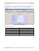
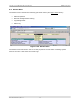
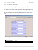
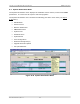
6.5.2 External Voltage Alarm Setting
The
External Voltage Alarm Setting page allows the user to set the voltage threshold for
each of the I/O port analog inputs (pins). Voltage 1 though Voltage 8 correspond to pins 1
though 8; pin 9 is ground.
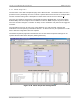
For example, the pin 6 settings (Voltage6 Trigger Polarity and Voltage6 Trigger Threshold)
seen in Figure 6-27
will create an alarm if the pin 6 output voltage is greater than 2.0 VDC.
NOTE: For this application, Pin 6 has been connected to the cabinet door switch contacts,
Pin 7 has been connected to the cabinet smoke detector and the Web interface has been
configured accordingly. The External Voltage Alarm Settings should not be modifies by the
user.
Figure 6-27 External Voltage Alarm Setting Configuration
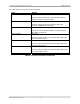
For each I/O pin, the user can set the following:
Item Selection
Voltage Trigger Polarity <, >
Voltage Trigger Threshold Range: 0.00 .. 10.00
Table 6-13 External Voltage Alarm Setting Parameters