
User's Manual Part 1

CL1TC-4 400W DVB-H Transmitter Commissioning and Operation
Product Manual, Rev. 1 45
5.6.1 Modulator
5.6.1.1 Front Panel
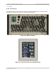
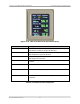
The t
wo line by forty characters LCD display, in conjunction with four cursor keys and an
EXECUTE button allow easy operation of the modulator. Three LED are provided as status
indicators. For a detailed description of front panel operation, please refer to Section 8.
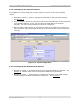
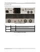
Figure 5-7 Modulator Front Panel
LED Description
POWER (Green) This Green LED indicates that the modulator AC power supply
has been turned on.
ALARM (Red) This Red LED indicates that there is an active transmitter
alarm.
UNLOCKED (Red) This Red LED indicates that the modulator has failed to
synchronize to the incoming transport stream or if the
incoming transport stream is absent.
NOTE: All LEDs flash green during the boot-up process.
Table 5-1 Modulator Front Panel Status LEDs
Pushbutton Function
EXECUTE Used to enter the configuration menu system (GENERIC or
SPECIFIC) from a status display window, to enter a sub-menu
and confirm changes made to configurable parameters.
c (up)
Used to scroll through the different status display windows,
exit the current menu and enter a higher-level menu, increase
alpha-numerical parameters or abort confirmation of a change.
d (down) Used to scroll through the different status display windows,
exit the current menu and enter a sub-menu, decrease alpha-
numerical parameters or abort confirmation of a change.
e (left)
f (right)
Used to scroll horizontally through the Config menus, the
parameter listings and the parameter characters, in the case of
editable parameters. They are also used to increase and
decrease % parameters.
Table 5-2 Modulator Front Panel Pushbutton Functions