
User's Manual Part 1

CL1TC-4 400W DVB-H Transmitter Installation
Product Manual, Rev. 1 34
4.7 Cabinet Sub-Assemblies
4.7.1 Modulator Installation
T
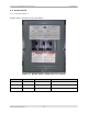
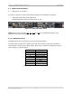
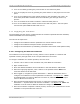
he user is required to connect the following cables to the modulator rear panel:
• GPS antenna RF cable to the GPS input
• WAN/LAN Ethernet cable to Ethernet port A or B
Figure 4-3 Modulator Rear Panel
NOTE: Please refer to sections 3.2
, 3.3, 3.4 and 3.5 for a detailed description of the
modulator rear panel interfaces.
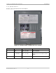
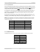
4.7.1.1 RS232 Serial Port
The RS232
serial port is configured to provide two Alarm Relays.
The alarm relay contacts are normally open and close on alarm; when the modulator is
turned off the contacts are normally closed. Each relay is software controlled and can be
set to trigger on a specific alarm.
Pin No Function
1 Relay 1 contact
2 RxD
3 TxD
4 Relay 2 contact
5 GND
6 Relay 1 contact
7 RTS
8 CTS
9 Relay 2 contact
Table 4-3 RS232 Serial Port Pin-out