
User's Manual Part 1

CL1TC-4 400W DVB-H Transmitter Installation
Product Manual, Rev. 1 30
4.4 Cabinet Installation
4.4.1 Installation Surface
Bef
ore installing the cabinet, check the installation surface structure, flatness and suitability.
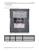
4.4.2 Cabinet Positioning
NOTE:
Please refer to site drawings for cabinet positioning.
• The cabinet should be positioned within the room to allow for adequate ventilation.
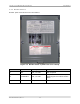
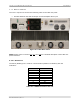
• Sufficient space must be made available in front of the cabinet so that the front door
can be opened and closed, allowing the user to access the playout server, modulator,
HPA and UPS front panels.
• Sufficient space must be made available to the rear of the cabinets so that the rear
door can opened and closed, allowing the user to access the playout server,
modulator, HPA and UPS rear panels, as well as the air conditioner control panel.
• Sufficient space must be made available to the left of the cabinet (when facing the
front of the cabinet) so that the breaker panels can be accessed.
• Sufficient space must be made available to the right of the cabinet (when facing the
front of the cabinet) so that the cable glands can be accessed.
For safety reasons, a minimum of four people is required for any lifting and/or positioning of
the transmitter. The transmitter is mounted on a pallet for easy movement using a pallet
pump truck.
4.5
Mains AC Power
NOTE:
Please refer to site drawings for the interconnection of the cabinet to the building
Mains AC distribution panel.
4.5.1 General
A cert
ified Electrician should install the Mains AC power cables to meet all regional and
national electrical codes, and according to the transmitter electrical drawing(s).
NOTE: Please refer to the cabinet vendor’s drawings for Mains AC and Frequency
specifications.
WARNING
VERIFY THAT THE MAINS AC VOLTAGE IS WITHIN
THE SPECIFIED RANGE AND CHECK ALL POWER
CABLES FOR DAMAGE