
User's Manual Part 1

CL1TC-4 400W DVB-H Transmitter Transmitter Technical Specifications
Product Manual, Rev. 1 24
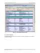
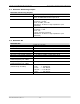
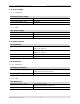
3.4 Modulator Monitoring Outputs
Modulator Monitoring Outputs
DVB-ASI 2 DVB-ASI outputs: BNC (F), 75 Ohm
RF Monitor Connector: SMA (M), 50 Ohm
Level: 30 dB below the RF output level
Clock Reference - 10 MHz Connector: BNC (F)
Frequency: 10 MHz
Level: 10 dBm, ±2.5 dB
Impedance: 50 Ohm or High Impedance (user
selectable)
Time Reference - 1 PPS Connector: BNC (F)
Frequency: 1 PPS
Level: TTL
Trigger: Positive transition
Impedance: 50 Ohm or High Impedance (user
selectable)
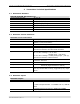
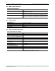
3.5 Modulator RF
Modulator RF
Connector
N-type (F), 50 Ohm
Frequency
1670 MHz to 1675 MHz
Power Level
-10 dBm to 0.0 dBm in 0.1 dB steps
Spectrum Polarity Inverted or non-inverted, selectable
Level Stability ± 0.3 dB
Shoulder Level < -55 dBc
Spurious Level Outside Channel < -60 dBm at 0 dBm output power level
MER ≥ 43 dB
Amplitude Flatness
Center frequency ±2.3 MHz
±0.5 dB
Group delay response:
Center frequency ±2.3 MHz
300 ns, ±100ns
Phase Noise SSB
(measured @ 474 MHz)
100 Hz: < -80 dBc/Hz
1 kHz: < -95 dBc/Hz
10 kHz: < -100 dBc/Hz
100 kHz: < -115 dBc/Hz
1 MHz: < -120 dBc/Hz
Return Loss > 20 dB