
User's Manual Part 1

CL1TC-4 400W DVB-H Transmitter Product Description
Product Manual, Rev. 1 21
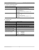
The following HPA factory control commands are available via USB:
• RF Power enable/disable
• Attenuator control
The HPA is a constant gain block, which is individually calibrated in order to maintain the RF
performance while operating in various conditions. The calibration is performed on the
forward power sensor, reflected power sensor and input power sensor. A calibration table is
stored in the internal EEPROM of the HPA controller.
The HPA controller reports alarms to the system controller and maintains an internal log of
alarms. Each alarm entry in this log contains the alarm ID itself along with monitored
parameters prior to an alarm. This alarm log is saved in an internal EEPROM.
2.4 Breaker Panels
T
he two (2) breaker panels are mounted on the left wall of the cabinet (when looking at the front
of the cabinet) in the top-left corner of the wall.
Circuit breaker panel 1 receives the input AC power and distributes the required power to circuit
breaker panel 2, as well as the air conditioner.
Circuit breaker panel 2 receives AC power (from circuit breaker panel 1) and distributes the
required power two (2) receptacles as well as the HPA. One of the receptacle provides AC power
to the UPS, internal lights and smoke detector; the other is a GFI.
2.5 Control Interfaces
T
he modulator serves as the primary system controller responsible for configuration and
management of the entire transmitter and interfaces. The physical interface for system
management is the modulator Ethernet port, which supports Web, SNMP v3 (secure SNMP), and
Telnet.
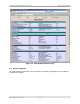
The modulator hosts an internal web interface (Web-GUI) accessible through its Ethernet
management port. The Web-GUI is an intuitive interface allowing the user to access the current
transmitter status and configure the operational parameters of the system. The Web interface
uses a simple hierarchical menu structure which provides access to all transmitter parameters.
Below is a snapshot of the main status screen of the Web-GUI.
The transmitter SNMP interface provides the means for remote management of the transmitter
and to accept alarm traps. The notification options can be configured on a per-alarm basis. The
user may decide to mask certain alarms, increase/decrease integration time to declare an alarm,
etc. Alarm and logs are available via the SNMP interface and are stored in Non Volatile Memory