
User's Manual Part 1


CL1TC-4 400W DVB-H Transmitter Product Description
Product Manual, Rev. 1 16
2.3.4.3 Bandpass Filter
Eac
h modulator is equipped with a narrow-band output filter specifically tuned to the frequency
channel assigned to the transmitter. The bandpass filter is intended to limit out-of-band
emissions at the output of the modulator’s internal amplifier.
2.3.4.4 GPS Receiver
The onboard GPS rece
iver provides accurate, high quality 10 MHz and 1PPS reference
signals for transmitter synchronization and has the capability to track 12 satellites. The 10
MHz and 1PPS reference signals are provided for the modulator board as well as one 10 MHz
and one 1 PPS reference signal for external devices.
The GPS receiver supports the NMEA formatted message protocol as well as the proprietary
NavMan binary messages. A subset of the protocols is used by the processor in order to
control the receiver.
The user has the option to set the Max GPS Holdover time, updated the system clock from
the GPS and set the time zone. Following a loss of signal lock (to the GPS satellite
network), the Max GPS Holdover time is the maximum length of time the system will
continue to operate in a free-running mode before an alarm is issued.
2.3.4.5 I/O Extension Board
The I/O extension board provides four (4) analog pull down inputs a
nd four (4) analog pull
up inputs, which are available on the rear panel I/O port. The analog inputs are monitored
by the system controller permitting the user to set the polarity and voltage threshold that
trigger an alarm.
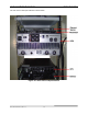
NOTE: For this application, Pin 6 has been connected to the cabinet door switch contacts,
Pin 7 has been connected to the cabinet smoke detector and the Web interface has been
configured accordingly.
2.3.4.6 Transmitter Controller Module
• P
rovides all primary site control and management functionality.
• Manages all control interfaces of the transmitter.
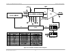
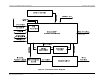
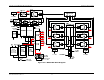
The modulator and HPA are connected by a RS-485 serial cable for control and monitoring
(see Figure 2-6
). The system controller supports transmitter operation, configuration,
management and status reporting. The control includes power up, power down, RF control
processes, control commands for status requests and operating parameters, etc. The
transmitter identity (name, password, local IP address, SNMP, etc.) can be configured
remotely or locally. Remote upgrade of the transmitter software is supported.
The system controller supports a web interface (Web GUI) for its user interface and is
responsible for software and configuration management. Remote control of the transmitter
is typically managed via an SNMP agent.