
System Description Chapter 2

4-6 kW UHF Translator Chapter 2, System Description
837B, Rev. 0 2-9
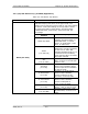
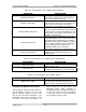
Table 2-8. UHF Amplifier Tray, LDMOS Status Indicators
INDICATOR DESCRIPTION
Enable (DS4 Green)
Indicates that an enable, Operate
command, is applied to the UHF amplifier
tray from the UHF exciter tray
Overdrive (DS2 Red)
Indicates that the level of the drive is too
high and the protection circuit will limit the
drive to the set threshold. This fault is
generated on the amplifier control board.
VSWR Cutback (DS1 Red)
Indicates that the reflected power level of
the tray has increased above 50% and the
output power level will automatically be cut
back to 20%. This fault is generated on the
amplifier control board.
Overtemp (DS3 Red)
Indicates that the temperature of (A5-A6-
A3 and A5-A6-A4), one or both of the two
thermal switches mounted on the heatsink
assembly for the output amplifiers, is above
175° F. When this fault occurs, the Enable
to the switching power supply in the
affected amplifier tray is removed
immediately and the tray will shut down.
Input Fault (DS5 Red)
Indicates that the input RF level to the
amplifier trays has dropped below the
0 dBm range
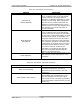
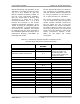
Table 2-9. UHF Amplifier Tray, LDMOS Control Adjustments
ADJUSTMENT DESCRIPTION
Phase (A10-R5)
Adjusts the phase of the RF output by
approximately 70%
Gain (A11-R6)
Adjusts the gain of the RF output when the
amplifier control board is in the AGC mode
Table 2-10. UHF Amplifier Tray, LDMOS Sample
SAMPLE DESCRIPTION
Module O/P (0 dBm)
A sample of the combined output of the
four dual-stage amplifier boards that is
taken from the dual peak detector board
2.3 Input and Remote Connections
The Baseband Video and Audio Inputs to
the Translator, connect to the (A9)
Remote Interface Panel located on the
rear of the UHF Exciter Assembly. The
Baseband Video Input connects to Jack
J2, which is loop-thru connected to J1,
that is wired to J1 on the Exciter. The
Baseband Audio Input connects to
Terminal Block TB1 for Balanced Audio or
to Jack J6, which is loop-thru connected
to J13, that is wired to J3 on the Exciter,
for Composite, Stereo, Audio.