
System Description Chapter 2

4-6 kW UHF Translator Chapter 2, System Description
837B, Rev. 0 2-8
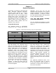
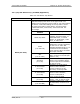
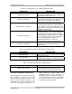
Table 2-6. UHF Exciter Tray Samples
SAMPLE DESCRIPTION
f(IF)
A sample of the visual IF that is taken from
the sample jack on the IF carrier oven
oscillator board
f(IC)
A sample of the intercarrier signal that is
taken from the sample jack on the aural IF
synthesizer board
f(s)
A sample of the channel oscillator output
that is taken from the sample jack of the
channel oscillator assembly
Exciter O/P
An output power sample of the exciter that
is taken from the UHF upconverter board
Translator O/P
A forward power sample of the translator
that is taken from the visual/aural metering
board
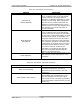
2.2.2 {A1, A2, A3, A4, A5(5kW) & A6(6kW} UHF Amplifier Trays, LDMOS
(1301560, low band/1301561, mid band/1301562, high band; Appendix C)
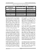
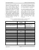
Table 2-7. UHF Amplifier Tray, LDMOS Meters
METER FUNCTION
This meter reads power in terms of a percent of the
calibrated power output value. A full-scale reading is
100%, which is equivalent to the full-rated 600 watts peak
of sync visual + aural output power. The meter also reads
the % Reflected Power, power supply voltage levels, and
AGC voltage levels.
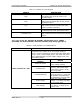
With Switch S2 in
Position
Display
Switch S2, Meter
Selects the desired % power
or the voltage reading
% Output Pwr
Reads the % Output Power of
the tray (100%=600 watts
peak of sync visual + aural)
on the top scale
% Refl (Reflected)
Reads the % Reflected Output
Power of the tray (<10% with
all amplifier trays operating)
as measured on the top scale
Power Supply
Reads the power supply
voltage >+30 VDC(+32 VDC)
on the middle scale
Meter (A1 thru A6 - A9)
AGC Voltage
Reads the AGC voltage level
(+1 VDC to +3 VDC) on the
bottom scale