
System Description Chapter 2

4-6 kW UHF Translator Chapter 2, System Description
837B, Rev. 0 2-4
Three phase connects, Line 1 to TB1-1A,
Line 2 to TB1-2A, Line 3 to TB1-3A and
Safety Ground to TB1-4A.
Single phase connects, Line 1 to TB1-1A,
Line 2 to TB1-3A and Safety Ground to
TB1-4A.
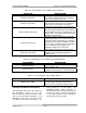
The AC Distribution Panel contains nine
Circuit Breakers that supply the AC to the
rest of the Amplifier Assembly. The
Input AC from TB1B is connected to
(CB1) the Main AC Circuit Breaker (55
Amps three phase or 100 Amps single
phase) that distributes the 208/240 VAC
to the other eight circuit breakers. The
output of CB1 has three MOVs, VR4 from
Line 1 to ground, VR6 from Line 2 to
Ground and VR3 connected across the
two lines for surge and over-voltage
protection. The switched Input AC is
wired through the Circuit Breakers, CB2-
CB7, via AC Line Cords to the six UHF
Amplifier Trays, LDMOS mounted in each
Amplifier Array Cabinet. CB2 is a 20
Amp Circuit Breaker that supplies the AC
voltage to the (A1) UHF Amplifier Tray.
CB3 is a 20 Amp Circuit Breaker that
supplies the AC voltage to the (A2) UHF
Amplifier Tray. CB4 is a 20 Amp Circuit
Breaker that supplies the AC voltage to
the (A3) UHF Amplifier Tray. CB5 is a 20
Amp Circuit Breaker that supplies the AC
voltage to the (A4) UHF Amplifier Tray.
In a 5kW configuration, CB6 is a 20 Amp
Circuit Breaker that supplies the AC
voltage to the (A5) UHF Amplifier Tray.
In a 6 kW configuration, CB7 is a 20 Amp
Circuit Breaker that supplies the AC
voltage to the (A6) UHF Amplifier Tray.
In 5 and 6 kW configurations, CB8 and
CB9 are 3 Amp Circuit Breakers that
supply AC to the two cooling fans
mounted in the Reject Load Assembly in
the Amplifier Array Assembly.
2.1.2.1 (A13) (Optional) External
Exhaust Kit (1061320)
Each of the 2-3 kW Amplifier Array
Assemblies may contain the (Optional)
(A13) External Exhaust Kit mounted on
the roof of the cabinets. This kit provides
greater cooling by venting the hot air
outside the Translator room using a
blower fan. +12 VDC is applied to TB1-
4A in the Exhaust enclosure when the
UHF Exciter circuit breaker is switched
On. An Enable is connected to TB1-3A
when the UHF Exciter, Translator, is
switched to Operate. The Enable
energizes the Isolation Relay that applies
the 120 VAC to the fan that will operate.
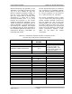
2.1.3 Translator Output Assemblies
The outputs of the (A2 & A3) 2-3 kW
Amplifier Assemblies (+63.5 to +65.2
dBm) connect through (A5 or A6) 1-5/8”
to 3-1/8” Adapters to (A4) a Hybrid
Combiner. The combiner combines the
output from each Amplifier Assembly into
a single output. The Reject Output of the
Hybrid Combiner is connected through
(A12) a 1-5/8” to 3-1/8” Adapter to (A7)
a Directional Coupler (1016-1043) that
provides a Reject Sample from J3 to the
Metering Panel located in the UHF Exciter
Assembly for monitoring purposes. The
output of the Directional Coupler
connects to (A8) a 2500 Watt Reject
Load which dissipates any reject due to
problems in one of the Amplifier Arrays.
Mounted on the 2500 Watt Load is (A8-
A1) a Thermal Switch that connects to
the Overtemperature Fault circuit located
on the Transmitter Control Board in the
UHF Exciter Tray. If the temperature of
the load reaches 155°F. the switch closes
and causes an Overtemperature Fault to
occur which shuts down the Translator.
The output of the Hybrid Combiner at J3
is fed through 3-1/8” hard line to (A9) a
Bandpass Filter, (A10) an Output Trap
Filter Assembly, then to (A11) the Output
Coupler Assembly and finally to the
Antenna for your System. The Bandpass
Filter and Trap Filter are tuned to provide
high out of band rejection of unwanted
generated products. The filtered signal is
connected to (A11) an Output Coupler
Assembly that provides a Combined
Forward and a Combined Reflected Power