
System Description Chapter 2

4-6 kW UHF Translator Chapter 2, System Description
837B, Rev. 0 2-3
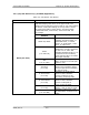
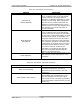
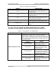
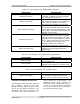
Table 2-2. Amplifier Array Trays and Assemblies
MAJOR ASSEMBLY
DESIGNATOR
TRAY/ASSEMBLY NAME PART NUMBER
A1, A2, A3, A4, A5(5kW) &
A6(6kW)
UHF Amplifier Trays, LDMOS
(Low Band) 1301560,
(Mid Band) 1301561,
Or (High Band) 1301562
A7 4, 5 or 6 Way Combiner Various
A8 Output Coupler Assembly 1016-1043
A12 Reject Load Assembly 1278-1312
A9-A1 8-Way Splitter 1245-1701 (ZFSC-8-43)
A10 AC Distribution Assembly
Three Phase 1278-1100
Or Single Phase 1278-1200
A11 Interface Assembly 1131532
The (A2 & A3) Amplifier Array Assemblies
each contain (A9-A1) an 8 Way Splitter
(ZFSC-8-43), four, five or six {A1, A2,
A3, A4, A5(5kW) & A6(6kW)} UHF
Amplifier Trays, LDMOS, (A7) a 4, 5 or 6
Way Combiner, (A12) a Reject Load
Assembly, (A8) an Output Coupler and
(A10) an AC Distribution Assembly, Three
Phase (1278-1100) or Single Phase
(1276-1200). The reject output from the
Combiner connects to (A12) a Reject
Load Assembly, which contains (A12-A2)
a Combiner Reject Load Board (1278-
1311) in a 5 or 6 kW configuration.
The RF Input (+16 dBm) from the
Variable Phase/Gain Tray connects to J1
on (A11) the Interface Panel located in
the Amplifier Array Assembly. The RF is
connected to the COM Input of (A9-A1)
the 8 Way Splitter that splits it eight
ways. The outputs (+6 dBm) connected
to J1, the RF Input Jack on each of the
UHF Amplifier Trays or are terminated
with 50Ω. Each of the UHF Amplifier
Trays amplify the RF signals to the power
needed to produce the total output power
for the Translator, with a maximum of
600 Watts per Tray. The outputs (+57.5
to +60 dBm) of the UHF Amplifier Trays,
LDMOS are combined in the (A7) 4, 5 or
6 Way Combiner assembly. The output
of the combiner is cabled to (A8) the
Output Coupler Assembly that supplies a
Forward and a Reflected Power Sample of
the output from the Amplifier Assembly
to the Metering Panel in the Single
Exciter Assembly. The reject output of
the Combiner, in a 5kW or 6kW
configuration, connects to (A12) the
Reject Load Assembly that dissipates any
reject due to miss-tuning or a
malfunction in any of the Amplifier Trays.
The RF Output of the Coupler at J2
(+63.5 to +65.2 dBm) is the RF output
of the 2-3 kW Amplifier Array.
In each UHF Amplifier Tray, a Forward
Power Sample and a Reflected Power
Sample, from the Combiner Board, are
connected to the Dual Peak Detector
Board, Single Supply. The Dual Peak
Detector provides peak detected forward
samples to the Amplifier Control Board
that supplies the samples to the front
panel meter of the UHF Amplifier Tray.
Before exiting each UHF Amplifier Tray
the RF is fed through a Circulator for
protection of the Tray from high VSWR
conditions. The Reject Port of the
Circulator provides a Reject Sample to
the Combiner Board which supplies the
Reflected Sample to the Dual Peak
Detector Board, Single Supply located in
the Tray that connects to the front panel
meter for monitoring purposes.
The 208/240 VAC Input to each Amplifier
Array Assembly connects to (A10) the AC
Distribution Assembly located on the
right side, center rear of the Cabinet.
The Assembly contains the Terminal
Block (TB1) to which the 208/240 Three
Phase or Single phase connects.