
System Description Chapter 2

4-6 kW UHF Translator Chapter 2, System Description
837B, Rev. 0 2-2
To select the output from the Modulator,
J8-10 and J8-11, must be connected
together.
The Exciter RF Output of the (A1) UHF
Exciter at J15 (+10 to +20 dBm) is
connected to the S Input on (A3) the
Splitter. The Exciter Output is split two
ways by A3 with RF Output #1
connected to the input of the (A5)
Variable Phase/Gain Tray (1245-1200)
and RF Output #2 connected to the
input of the (A4) Variable Phase/Gain
Tray (1245-1200).
The Variable Phase/Gain Tray sets the
phase and gain adjustments of the RF to
provide maximum output when the
outputs of the two Amplifier Arrays are
combined. The output of the (A4)
Variable Phase/Gain Tray (+16 dBm)
connects to (A2) the Side A 2-3 kW
Amplifier Array Assembly. The output of
the (A5) Variable Phase/Gain Tray
(+16 dBm) connects to (A3) the Side B
2-3 kW Amplifier Array Assembly.
The 208/240 VAC Input to the UHF
Exciter Assembly connects to (A8) the AC
Distribution Assembly, UHF Exciter
Assembly (1245-1500) located in the
right, center rear of the Cabinet. The
Assembly contains the Terminal Block
(TB1) to which the 208/240 VAC
connects. Line 1 to TB1-1A, Line 2 to
TB1-3A and Safety Ground to TB1-2A.
The AC Distribution Assembly contains
(CB1) the Main Circuit Breaker (20
Amps) that supplies the AC to the rest of
the Single Exciter Assembly. The output
of CB1 has three MOVs, VR1, VR2 and
VR3, connected to it, VR1 from Line 1 to
ground, VR3 from Line 2 to ground and
VR2 connected across the two lines. The
AC output of CB1 is wired to A1 and A2
that are IEC Outlet Strips. The (A1)
Exciter and the (A4) Variable Phase/Gain
Tray plug into the (A1) IEC Outlet Strip.
The (A5) Variable Phase/Gain Tray, the
(A6) Metering Panel and the (A7)
Receiver Tray plug into the (A2) IEC
Outlet Strip.
When the Circuit Breaker CB1 on the
Single UHF Exciter Assembly is switched
On, +12 VDC from the Exciter is
connected to A9-TB1 in each of the
Amplifier Array Cabinets. The +12 VDC
is split 4-6 Ways on the terminal block
A9-TB1 and connected to each of the
UHF Amplifier Trays at J3-7. The +12
VDC is used for operation of the LED
Status Indicators in the UHF Amplifier
Tray. The +12 VDC is also connected to
J4-20 and then to A9-TB2 for the
(Optional) External Exhaust Kit in each
Amplifier Array. When the UHF Exciter
Tray, Translator, is switched to Operate,
an Enable is applied to each of the 2-3
kW Amplifier Arrays at J4-15 that
connects to A9-TB2. The Enable is split
4-6 Ways on the terminal block A9-TB2
and connected to each of the UHF
Amplifier Trays at J3-9. This Enable
turns on the +32 VDC Power Supply in
each Amplifier Tray. Also a Fan Enable is
connected to J4-19 and then to A9-TB2
that connects to the (Optional) External
Exhaust fan mounted on the roof of each
Amplifier Array Cabinet, turning it On.
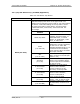
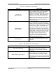
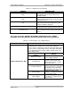
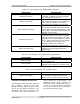
2.1.2 (A2 & A3) 2-3 kW Amplifier
Arrays (1278-1300; Appendix C)
The (A2 & A3) 2-3-kW Amplifier Arrays
are identical and are made up of the
trays and assemblies listed in Table 2-2.