
System Description Chapter 2

4-6 kW UHF Translator Chapter 2, System Description
837B, Rev. 0 2-13
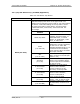
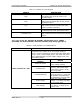
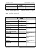
FUNCTION REMOTE JACK/PIN
NUMBER
INTERFACE TYPE
Remote Metering
(A4) UHF Amplifier Tray Forward
Output Power
J5-13
(A4) UHF Amplifier Tray Forward
Output Power Rtn
J5-14
1V full scale at 1kΩ source
resistance
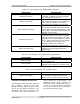
(A4) UHF Amplifier Tray Reflected
Output Power
J5-15
(A4) UHF Amplifier Tray Reflected
Output Power Rtn
J5-16
1V full scale at 1kΩ source
resistance
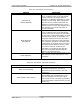
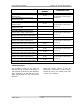
(A5) UHF Amplifier Tray Forward
Output Power (5kW configuration)
J5-18
(A5) UHF Amplifier Tray Forward
Output Power Rtn(5kW configuration)
J5-17
1V full scale at 1kΩ source
resistance
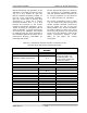
(A5) UHF Amplifier Tray Reflected
Output Power(5kW configuration)
J5-21
(A5) UHF Amplifier Tray Reflected
Output Power Rtn(5kW configuration)
J5-20
1V full scale at 1kΩ source
resistance
(A6) UHF Amplifier Tray Forward
Output Power(6kW configuration)
J5-22
(A6) UHF Amplifier Tray Forward
Output Power Rtn(6kW configuration)
J5-23
1V full scale at 1kΩ source
resistance
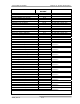
(A6) UHF Amplifier Tray Reflected
Output Power(6kW configuration)
J5-24
(A6) UHF Amplifier Tray Reflected
Output Power Rtn(6kW configuration)
J5-25
1V full scale at 1kΩ source
resistance
2.4 Main AC Input
The Translator needs an AC input of
208/240 VAC @ 55 Amps Three Phase or
100 Amps Single Phase for each Amplifier
Array Assembly and 208/240 VAC @ 20
Amps Single Phase for the UHF Exciter
Assembly.
These AC Inputs connect to the AC
Distribution Assemblies located facing
toward the rear in the middle, right side
of each of the cabinets.