
System Description Chapter 2

4-6 kW UHF Translator Chapter 2, System Description
837B, Rev. 0 2-12
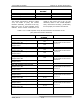
FUNCTION REMOTE JACK/PIN
NUMBER
INTERFACE TYPE
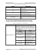
Remote Metering
Combined Reject Power J10-11
Combined Reject Power Rtn J10-12
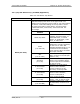
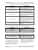
The remote connections, shown in Table
2-13, are made to (A11) the remote
interface assembly, mounted at the top,
facing the rear of each Amplifier Array
Cabinet. These remote connections are
made to jack J5(37 Pos D con) on the
assembly. Refer to the 2-3kW amplifier
array interconnect drawing (1278-8300)
for the proper pin remote connections.
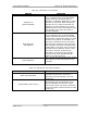
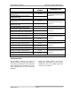
Table 2-13. 2-3 kW Amplifier Array Remote Interface Connections to the
(A11) Remote Interface Assembly
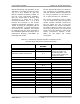
FUNCTION REMOTE JACK/PIN
NUMBER
INTERFACE TYPE
Remote Metering
(A1) UHF Amplifier Tray Reflected
Output Power Rtn
J5-1
(A1) UHF Amplifier Tray Reflected
Output Power
J5-2
1V full scale at 1kΩ source
resistance
(A1) UHF Amplifier Tray Forward
Output Power Rtn
J5-3
(A1) UHF Amplifier Tray Forward
Output Power
J5-4
1V full scale at 1kΩ source
resistance
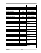
(A2) UHF Amplifier Tray Reflected
Output Power Rtn
J5-5
(A2) UHF Amplifier Tray Reflected
Output Power
J5-6
1V full scale at 1kΩ source
resistance
(A2) UHF Amplifier Tray Forward
Output Power Rtn
J5-7
(A2) UHF Amplifier Tray Forward
Output Power
J5-8
1V full scale at 1kΩ source
resistance
(A3) UHF Amplifier Tray Reflected
Output Power
J5-9
(A3) UHF Amplifier Tray Reflected
Output Power Rtn
J5-10
1V full scale at 1kΩ source
resistance
(A3) UHF Amplifier Tray Forward
Output Power
J5-11
(A3) UHF Amplifier Tray Forward
Output Power Rtn
J5-12
1V full scale at 1kΩ source
resistance