
Data Sheet Chapter 5

4-6 kW UHF Translator Chapter 5, Detailed Alignment Procedures
837B, Rev. 0 5-8
4. Connect a 5-step staircase video
test signal to the input of the
transmitter.
5. Monitor TP2 with an oscilloscope.
Adjust R12, the video gain pot, for
1 Vpk-pk.
6. Change the video input test signal
to a multiburst test pattern. While
monitoring TP2, adjust C8 and R32
for a flat-frequency response.
Change the input video test signal
back to the 5-step staircase.
7. Monitor TP2 with an oscilloscope.
Adjust the pot R41, manual offset,
for a blanking level of -0.8 VDC.
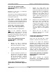
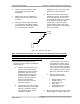
The waveform in Figure 5-1 should
be observed at this point. Move
jumper W2 on J4 to the clamp
enable position. Adjust pot R152,
depth of modulation, for a blanking
level of -0.8 VDC.
0
V
o
lt
s
.1 Volts
Figure 5-1. Waveform at TP2.
Note: The waveform in Figure 5-1 represents the theoretical level for proper
modulation depth. Step 8 below describes how to set the modulation depth
through the use of a television demodulator or a zero-spanned spectrum
analyzer tuned to the visual IF frequency.
8. The following test setup is for the
adjustment of the depth of modulation
and ICPM at IF:
A. Remove the cable that is now
on J18. Connect the double
sideband 45.75-MHz visual IF
signal from J18 to a 10-dB
splitter/coupler. Connect the
coupled port of the splitter/
coupler to the RF input of a
television demodulator.
Connect the direct port to a
spectrum analyzer.
B. Connect the 75-Ω video output
of the demodulator to the video
input of a waveform monitor.
For incidental carrier phase
modulation (ICPM)
measurements, also connect
the quadrature output of the
demodulator to the horizontal
input of the waveform monitor
using a 250-kHz low-pass filter.
(An oscilloscope can be used in
place of a waveform monitor).
C. Set the controls of the
demodulator as follows:
• Detector Mode: Cont
• Sound Trap: In
• Zero Carrier: On
• Auto: Sync
• Audio Source: Split
• De-Emphasis: In
9. Move jumper W7 on J4 to the clamp
disable position. Readjust pot R41,