
Assembly Instructions Chapter 4

4-6 kW UHF Translator Chapter 4, Circuit Descriptions
837B, Rev. 0 4-44
control board and is connected to the
dual peak detector board. F7 is a 15-
amp and F8 is a 3-amp spare fuse.
The +32 VDC from the switching power
supply enters the board at TB1, with
the plus (+) connections sent to pins 1
to 4 and the minus (-) connections sent
to pins 5 and 6. The +32 VDC is
connected across the .01-W/3-Ω
voltage-dropping resistors R14 to R26
that are used to set up the idling
currents for the transistor devices; the
fuses F1 to F6 that protect the
transistor devices during an
overcurrent condition through the
outputs of the board at TB2, TB3; and
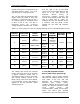
also to output jack J1. Table 4-1
indicates the fuse, the amplifier device
it protects, and the idling current
settings for the class AB amplifier
devices.
Table 4-1. Fuses, Idling Currents, and Voltage Settings for the Class AB Amplifier Devices
SWITCH
POSITION
AMPLIFIER
MODULE
LDMOS
DEVICE
BIAS
ADJUST
POT
IDLING
CURRENT
VOLTAGE
SETTING
FUSE
A3-A1*
Q1*
Transistor
NONE
.65A*
operating
current
I1
A4-A1 V804 & V805
R807 &
R808
.5A
11.5mV F1 10A
I2 A4-A3 V1 & V2 R206 2A 20mV F2 10A
I3 A5-A2 V1 & V2
R9, R11
& R12
2A 20mV F3 15A
I4 A5-A3 V1 & V2
R9, R11
& R12
2A 20mV F4 15A
I5 A5-A4 V1 & V2
R9, R11
& R12
2A 20mV F5 15A
I6 A5-A5 V1 & V2
R9, R11
& R12
2A 20mV F6 15A
*The A3-A1 transistor Q1 operates class A at .65 amps of operating current.
The voltage drop across the selected
resistor that uses switch S1 is read with
a digital voltmeter (DVM) that is
connected from E2 to E3 on the board.
This voltage reading converts to the
idling current, with no RF drive applied,
or the operating current, with RF drive
applied, of the Q1 transistor device
operating Class A.
4.7.15 (A8) Amplifier Control
Board (1265-1414; Appendix D)
The amplifier control board provides
LED fault and enable indications on the
front panel of the tray and also
performs the following functions:
automatic gain control (AGC);
overdrive cutback, when the drive level
reaches the amount needed to attain
110% output power; and
overtemperature, VSWR, and overdrive
faults. The board also provides
connections to the front panel meter for