
Assembly Instructions Chapter 3

4-6 kW UHF Translator Chapter 3, Installation and Setup Procedures
837B, Rev. 0 3-8
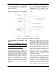
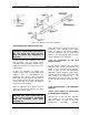
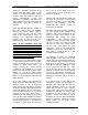
Figure 3-3 Typical Rigid Coax Reconnection Drawing
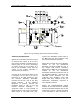
3.4 Setup and Operation
Initially, the translator should be turned
on with the RF output at J2 of (A11)
the coupler assembly terminated into a
dummy load of 4 to 6 kW, depending
on output power of your system. If a
load is not available, check that the
output of the coupler assembly is
connected to the antenna.
Connect the on channel RF Input to the
F connector J3 for 75Ω or to the N
connector J1 for 50Ω located on (A9)
the Remote Interface Assembly,
mounted on the top, rear of the UHF
Exciter Cabinet. If the Optional
Modulator is present, connect the
baseband audio to TB1 on the A9
remoter interface assembly. If
composite audio is used instead of
Balanced Audio, connect the Composite
Audio Input to the BNC Jack (J6).
Connect the Baseband Video Input to
the BNC Jack (J2) also located on (A9)
the Remote Interface Assembly.
Switch On the Main AC Circuit Breaker
located on the AC Distribution
Assembly mounted toward the rear of
the Single UHF Exciter Assembly.
Switch On the Main AC Circuit Breakers
located on the AC Distribution
Assemblies mounted toward the rear of
the Amplifier Cabinets. Switch On the
CB2-CB9 Circuit Breakers, for the
individual UHF Amplifier Trays and
Reject load fans, located on the AC
Distribution Assemblies mounted in
each Amplifier Cabinet.
Switch the Operate/Standby Switch
located on the UHF Exciter to Standby
and the Auto/Manual Switch also on the
UHF Exciter to Auto. Normal operation
of the Translator is with the switch in