
Assembly Instructions Chapter 3

4-6 kW UHF Translator Chapter 3, Installation and Setup Procedures
837B, Rev. 0 3-7
Assembly (1278-1100), located near the
center right hand side, rear portion of
Cabinet #2. Connect Line 1 to TB1-1A,
Line 2 to TB1-2A, Line 3 to TB1-3A and
Safety Ground to TB1-4A.
Connect the other 55 Amp, 208/240 VAC
Input to the Terminal Block A10-TB1,
which is part of the AC Distribution
Assembly, Amplifier Assembly (1278-
1100), located near the center right hand
side, rear portion of Cabinet #3.
Connect Line 1 to TB1-1A, Line 2 to TB1-
2A, Line 3 to TB1-3A and Safety Ground
to TB1-4A.
3.3.2.2 Single Phase AC Installation
to the Amplifier Cabinets
Connect one of the 100 Amp, 208/240
VAC Inputs to the Terminal Block
A10-TB1, which is part of the AC
Distribution Assembly, Amplifier
Assembly (1278-1200), located near the
center right hand side, rear portion of
Cabinet #2. Connect Line 1 to TB1-1A,
Line 2 to TB1-3A and Safety Ground to
TB1-4A.
Connect the other 100 Amp, 208/240
VAC Input to the Terminal Block
A10-TB1, which is part of the AC
Distribution Assembly, Amplifier
Assembly (1278-1200), located near the
center right hand side, rear portion of
Cabinet #3. Connect Line 1 to TB1-1A,
Line 2 to TB1-3A and Safety Ground to
TB1-4A.
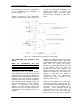
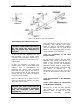
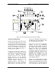
3.3.3 Output Connections
(Refer to Figure 3.3)
The RF Output of the (A2) Amplifier
Assembly connects through (A5) a 1-5/8"
to 3-1/8" Adapter to J1 on (A4) the
Hybrid Combiner. The RF Output of the
(A3) Amplifier Assembly connects
through (A6) a 1-5/8" to 3-1/8" Adapter
to J2 on (A4) the Hybrid Combiner. The
Reject Output of the combiner at J4
connects through (A12) a 1-5/8” to 3-
1/8” Adapter to (A7) a Directional
Coupler (1016-1043) to (A8) a 2500
Watt Reject Load. The combined RF
Output of the Combiner at J3 (3-1/8”)
connects through (A9) the Bandpass
Filter, (A10) the Output Trap Filter to
(A11) the Output Coupler Assembly
(1020-1002). The output of the coupler
at J2 (3-1/8”) connects to the
Transmission Line that is connected to
your Antenna System.
This completes the unpacking and
installation of the 837B UHF television
translator. Refer to the setup and
operation procedures that follow before
applying power to the translator.