
Assembly Instructions Chapter 3

4-6 kW UHF Translator Chapter 3, Installation and Setup Procedures
837B, Rev. 0 3-6
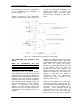
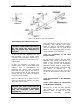
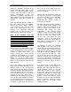
Figure 3-2. Chassis Trak Cabinet Slides
3.3 Installing the Cabinets and Trays
Caution: Each UHF amplifier tray has
a hardline coaxial cable connected to
the rear panel. The trays will not
slide out unless this connection is
removed.
To pull out the UHF amplifier trays for
test purposes, use the coaxial cable
included in the installation material kit to
make the connection from the tray to the
output cable.
It may be necessary to adjust the
position of the trays to keep them from
rubbing. This is accomplished by
loosening the cabinet slide mounting
bolts that hold the front of the slide to
the mounting frame of the cabinet and
moving the tray up or down, as needed,
to correct for the rubbing.
Once the cabinets are in place, and the
trays are checked for rubbing, the main
AC hookup can be made.
Caution: Before connecting the
208/240 VAC, make certain that all
of the circuit breakers associated
with the translator have been
switched off.
There are three AC Input circuits to the
Translator, one 208/240 VAC single
phase 20 Amp for the Exciter Cabinet
and two 208/240 VAC 55 Amp three
phase or 100 Amp single phase for each
of the Amplifier Array Cabinets.
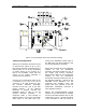
3.3.1 AC Connection to the UHF
Exciter Cabinet
In the Exciter Cabinet, the 20 Amp,
208/240 VAC Input connections are
made to the Terminal Block A8-TB1,
which is part of the AC Distribution
Assembly, Exciter Cabinet (1245-1500),
located near the center right hand side,
rear portion of Cabinet #1. AC
connections are, Line 1 to TB1-1A, Line 2
to TB1-3A and Chassis Ground to TB1-
2A).
3.3.2 AC Connection to the Amplifier
Cabinets
3.3.2.1 Three Phase AC Connection
to the Amplifier Cabinets
Connect one of the 55 Amp, 208/240
VAC Inputs to the Terminal Block
A10-TB1, which is part of the AC
Distribution Assembly, Amplifier