
Assembly Instructions Chapter 3

4-6 kW UHF Translator Chapter 3, Installation and Setup Procedures
837B, Rev. 0 3-5
Cabinet and the A3 Side B Amplifier
Cabinet. The Amplifier Arrays may have
an (Optional) External Exhaust Kit for
connection to duct work and the outside
of the building.
The cabinets should be positioned with
consideration taken for adequate air
intake and exhaust to the duct work, the
opening of the rear door, access to the
Trays including sliding them out for
testing, the AC hook up and the
installation of the Output Transmission
Line. The Cabinets should be Grounded
using copper strapping material and also
should be permanently mounted to the
floor of the Site using the holes in the
bottom of the Cabinets.
Remove the two L-brackets, mounted on
the front panel rails of the Single Exciter
Cabinet and Amplifier Cabinets, which
hold the Trays in place during shipment.
Inspect for any loose hardware or
connectors, tightening where needed.
Open the rear doors, the key to unlock
the door, if the door has the Optional
lock, is found in a tan envelope taped to
the door, and inspect the interior for
packing material. Carefully remove any
packing material that is found. Slowly
slide each Tray in and out to verify that
they do not rub against each other and
have no restriction to free movement.
Note: The UHF Amplifier Trays, if
removed, must be placed into the
Cabinets in the proper location
according to the labeling on each
Tray or the Gain and the Phasing will
not be maximized.
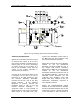
The UHF Amplifier Trays are labeled to
indicate where they are positioned in the
Side A or the Side B Amplifier Cabinets.
They are mounted in each Cabinet from
bottom left to top right, with A1 the
bottom left Tray and A6 the top right
Tray. The Tray labeled A1 is in the Side
A Cabinet, bottom left position. The Tray
labeled A2 is in the Side A Cabinet,
bottom right position. The Tray labeled
A3 is in the Side A Cabinet, center left
position. The Tray labeled A4 is in the
Side A Cabinet, center right position. If
present, the Tray labeled A5 is in the
Side A Cabinet, top left position. If
present, the Tray labeled A6 is in the
Side A Cabinet, top right position.
The UHF Amplifier Tray labeled B1 is in
the Side B Cabinet, bottom left position.
The Tray labeled B2 is in the Side B
Cabinet, bottom right position. The Tray
labeled B3 is in the Side B Cabinet,
center left position. The Tray labeled B4
is in the Side B Cabinet, center right
position. If present, the Tray labeled B5
is in the Side B Cabinet, top left position.
If present, the Tray labeled B6 is in the
Side B Cabinet, top right position.
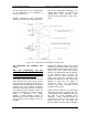
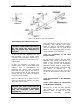
The trays are mounted in the cabinet
using Chassis Trak cabinet slides as
shown in Figure 3-2.
The tray slides are on the top and the
bottom of the UHF amplifier trays and on
the sides of the UHF exciter tray and the
Variable Phase/Gain Trays. Inspect the
trays for any loose hardware or
connectors, tightening as needed.