
Assembly Instructions Chapter 3

4-6 kW UHF Translator Chapter 3, Installation and Setup Procedures
837B, Rev. 0 3-4
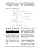
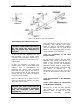
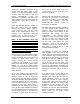
A 1 kW typical layout for a combination
of air conditioning and ventilation is
shown in Figure 3-1.
System interlocking and thermostat
settings should be reviewed with Axcera.
As with any equipment installation, it is
always good practice to consult the
manufacturer when questions arise.
Axcera can be contacted at (724) 873-
8100
Figure 3-1. 1 kW Minimum Ventilation Configuration
3.2 Unpacking the Cabinets and
Trays
Note: Air conditioning and any
related heat exhaust ducts should be
in place before continuing with the
installation of the translator.
Thoroughly inspect the cabinets and all
other materials upon their arrival. Axcera
certifies that upon leaving our facility the
equipment was undamaged and in proper
working order. The shipping containers
should be inspected for obvious damage
that indicates rough handling. Check for
dents and scratches or broken switches,
meters, or connectors. Any claims
against in-transit damage should be
directed to the carrier. Inform Axcera as
to the extent of any damage as soon as
possible.
Remove the Cabinets with Trays, Hybrid
Combiner and Output Coupler along with
the Installation Material that make up the
837B from the crates and boxes.
Remove the straps that hold the cabinets
to the shipping skids and slide the
cabinets from the skids. Remove the
plastic wrap and foam protection from
around the cabinets. Do not remove any
labeling or tags from any cables or
connectors; these are identification
markers that make assembly of the
translator much easier.
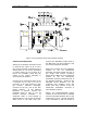
There are three Cabinets, (A1) the Single
UHF Exciter Assembly, (A2) the Side A 2-
3 kW Amplifier Array Assembly and (A3)
the Side B 2-3 kW Amplifier Array
Assembly. These Cabinets should be
arranged from left to right with you
facing the front, the A1 Single UHF
Exciter Cabinet, the A2 Side A Amplifier