
User Manual

835A 4 kW, 5 kW or 6 kW UHF Transmitter Remote Control Interface Connections
- Page 2 of 3 -
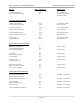
Exciter Remote Status Indications: - Continued
Video Loss Indicator J9-7 50ma Max. Current Sink
Video Loss Indicator Rtn J9-8
Receiver Fault Ind. J8-9 50ma Max. Current Sink
Side A Driver Remote Metering:
Side A Driver Output Power J10-1 1V Full Scale At 1kΩ
Side A Driver Output Power Rtn J10-2 Source Resistance
Side B Driver Remote Metering:
Side B Driver Output Power J10-3 1V Full Scale At 1kΩ
Side B Driver Output Power Rtn J10-4 Source Resistance
Side A Remote Metering:
Side A Forward Power J10-14 1V Full Scale At 1kΩ
Side A Forward Power Rtn J10-15 Source Resistance
Side A Reflected Power J10-16 1V Full Scale At 1kΩ
Side A Reflected Power Rtn J10-17 Source Resistance
Side B Remote Metering:
Side B Forward Power J10-20 1V Full Scale At 1kΩ
Side B Forward Power Rtn J10-21 Source Resistance
Side B Reflected Power J10-18 1V Full Scale At 1kΩ
Side B Reflected Power Rtn J10-19 Source Resistance
Side A Plus B Remote Metering:
Reject Power J10-11 1V Full Scale At 1kΩ
Reject Power Rtn J10-12 Source Resistance
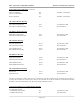
The above connections are made to Jack (J9), the 37 Position "D" Connector, to Jack (J10), the 25 Position "D" Connector, to
Jack (J8), the 25 Position "D" Connector Or to Jack (J7), the 9 Position "D" Connector, located on (A9) the Remote Interface
Assembly (1245-1801) mounted at the Top, Rear of the Single UHF Exciter Cabinet.
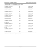
(A2 and A3) Amplifier Array Assembly Remote Metering
for 4 kW, 5 kW & 6 kW
(A1) UHF Amp Tray Refl Pwr J5-2 1V Full Scale At 1kΩ
(A1) Reflected Power Rtn J5-1 Source Resistance