
User Manual
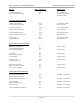

835A 4 kW, 5 kW or 6 kW UHF Transmitter Remote Control Interface Connections
- Page 1 of 3 -
Function Remote Jack/Pin No. Interface Type
Exciter Enable Interlock J7-1 J7-1 & 2 Must Be
Exciter Enable Interlock Rtn. J7-2 Jumpered Together For
Normal Operation.
Transmitter Remote Metering:
Combined Visual Power J10-7 1V Full Scale At 1kΩ
Combined Visual Power Rtn J10-8 Source Resistance
Combined Aural Power J10-5 1V Full Scale At 1kΩ
Combined Aural Power Rtn J10-6 Source Resistance
Combined Reflected Power J10-9 1V Full Scale At 1kΩ
Combined Reflected Power Rtn J10-10 Source Resistance
Exciter Output J9-26 1V Full Scale At 1kΩ
Exciter Output Rtn J9-27 Source Resistance
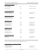
Exciter Remote Control Commands:
Exciter Operate (Enable) J8-3 Contact Closure
Exciter Standby/Operate Rtn. J8-2
Exciter Standby (Disable) J8-1 Contact Closure
Exciter Auto J8-6 Contact Closure
Exciter Auto/Manual Rtn. J8-5
Exciter Manual J8-4 Contact Closure
Modulator Select J8-10 Contact Closure
Modulator Select Rtn J8-11
Power Raise (Optional) J9-6 Contact Closure
Raise/Lower Rtn. (Optional) J9-5
Power Lower (Optional) J9-4 Contact Closure
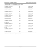
Exciter Remote Status Indications:
Exciter Auto Mode Indicator J9-30 50ma Max. Current Sink
Auto/Manual Mode Ind. Rtn J9-31
Exciter Manual Mode Indicator J9-32 50ma Max. Current Sink
Operate Indicator J9-1 50ma Max. Current Sink
Operate/Standby Ind. Rtn J9-2
Standby Indicator J9-3 50ma Max. Current Sink
Exciter VSWR Cutback Indicator J8-7 50ma Max. Current Sink