
Data Sheet Chapter 4

3-kW UHF Transmitter Chapter 4, Detailed Alignment Procedures
835-3, Rev. 0 4-9
The board is adjusted to give a peak-detected output indication to the front panel meter
for combined output, visual-only output, aural-only output, and reflected output. The
board should need no adjustments to achieve normal operation.
4.1.12 (A3-A2) +12-VDC(4A)/-12-VDC(1A) Power Supply Board (1227-1203;
Appendix B)
This board is mounted in (A3) the +12V(4A)/-12V(1A) power supply assembly (1227-
1210).
The board has no adjustments.
DS1 will be lit if a +12-VDC output is connected to J2. DS2 will be lit if a +12-VDC
output is connected to J3. DS3 will be lit if a +12-VDC output is connected to J4. DS4
will be lit if a +12-VDC output is connected to J5. DS5 will be lit if a –12-VDC output is
connected to J6.
4.2 (A1, A2, A3, A4, A5, and A6) 600-Watt UHF Amplifier Trays (1227-1300;
Appendix A)
The trays have been adjusted at the factory to meet all specifications, including phase
adjustment with other 600-watt amplifier trays, and should not need to be adjusted to
attain normal operation. During adjustments of the amplifier boards, switch S1 on the
amplifier control board should be in the Manual Gain position. The output voltage from
(A12) the switching power supply should be adjusted for +29.5 VDC.
4.2.1 (A1) UHF Filter (1007-1101; Appendix B)
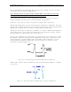
Apply a multiburst test signal to the transmitter. Monitor J2 with a spectrum analyzer
and tune C1 and C3 for peak output with a flat-frequency response.
4.2.2 (A2-A1) Variable Gain/Phase Board (1227-1330; Appendix B)
This board is mounted in the variable gain/phase enclosure (1227-1331).
There are no adjustments to this board; it has an adjustable gain of 0 to 20 dB.
4.2.3 (A3-A1) 1-WatT UHF Amplifier Board (1227-1303; Appendix B)
This board is mounted in the 1-watt amplifier enclosure (1227-1319).
The board has approximately 10 dB of gain and has no adjustments.
4.2.4 (A4-A1) Dual Stage Amplifier Board, Class A (1227-1305; Appendix B)
This board is part of the dual stage amplifier assembly, class A (1227-1340). The board
operates class A and has a gain of approximately 11 dB.
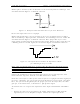
The biases of the transistors are set by the on-board biasing circuits. Adjust R106 and
R206 for 3 amps of idle current, no RF drive applied. Connect a voltage meter across E1
and E2 on the amplifier protection board. Move switch S1 to the I2 position and adjust
R106 for a reading of 30 mV. Move switch S1 to the I1 position and adjust R206 for a
reading of 30 mV.