
Data Sheet Chapter 4

3-kW UHF Transmitter Chapter 4, Detailed Alignment Procedures
835-3, Rev. 0 4-8
If a spectrum analyzer is not available, connect a digital voltmeter (DVM) to TP1 on the
x8 multiplier board. Tune capacitors C6 and C18 for maximum voltage and then also
tune L2 and L4 for maximum voltage output at TP1.
Connect the sample output of the channel oscillator, J2 to a suitable counter and tune
C11, coarse adjust, and C9, fine adjust, to the crystal frequency.
Note: Do not re-peak C6, C18, L2, or L4 because this may change the output
level.
Note: While adjusting C9 and C11 to the crystal frequency, the peak voltage
monitored at TP1 of the x8 multiplier board should not decrease. If a decrease
does occur, there may be a problem with the crystal. Contact ADC Field Support
for further instructions.
Note: If the VCXO board (1145-1204) in the VCXO assembly (1145-1206) is
used, C9, the fine-frequency adjust, is not located on the VCXO board, but on
the FSK identifier board by using R18.
Reconnect the main output, J1, of the channel oscillator to the input, J1, of the x8
multiplier board.
4.1.10 (A15-A1) x8 Multiplier Board (1227-1002; Appendix B)
This board is mounted in a x8 multiplier enclosure assembly (1227-1240).
During normal operation, the green LED DS1, which can be seen through the access
hole in the enclosure assembly, will be lit to indicate that the LO is present at the output
of the x8 multiplier board.
To align this board, connect a spectrum analyzer to the output jack, J2, of the board.
Tune C4, C6, C10, C12, C18, and C20 for maximum output. Readjust all of the
capacitors to minimize the seventh and the ninth harmonics; they should be at least -30
dB down
without affecting the x8 multiplier output.
If a spectrum analyzer is not available, a DC voltmeter can be used, but the harmonic
frequencies must be minimized to prevent interference with other channels.
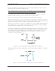
While monitoring each test point with a DC voltmeter, maximize each test point by
tuning the broadband multipliers in the following sequence:
•
Monitor TP1 with a DVM and tune C4 for maximum (typically 0.6 VDC)
•
Monitor TP2 and tune C6 and C10 for maximum (typically 1.2 VDC)
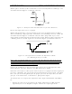
•
Monitor TP3 and tune C12 and C18 for maximum (typically 2.0 VDC)
•
Monitor TP4 and tune C20 for maximum
•
Re-peak C12 and C10 while monitoring TP4 (typically 3.5 VDC)
•
The typical output level is +15 dBm.
4.1.11 (A19-A1) Visual/Aural Metering Board (1227-1202; Appendix B)
This board is mounted in a visual/aural metering enclosure assembly (1227-1212).