
Data Sheet Chapter 4

3-kW UHF Transmitter Chapter 4, Detailed Alignment Procedures
835-3, Rev. 0 4-7
Input a multiburst video test signal. Remove the plug from J8 and connect a spectrum
analyzer. Tune C63 for a flat-frequency response of ±0.5 dB. Reconnect the plug to J8.
Move the Operate/Standby switch on the front panel to the Operate position.
Place jumper W3 on jack J6 in the Manual mode (towards the top of the board) and
adjust R87 for 0.8 volts at J19, pin 2, or at TP4.
Place jumper W3 on J6 in the Auto mode (towards the bottom of the board) and adjust
front panel power adjust control A20 fully CW. If the optional remote power raise/lower
kit is present, adjust switch S1 on the board to maximum voltage at J19, pin 2, or at
TP4. Adjust R74, the range adjust, for 1 volt at TP4.
Adjust front panel power adjust control A20 for 0.8 VDC at J19, pin 2, or at TP4. If the
optional remote power raise/lower kit is present, adjust switch S1 on the board to the
mid-range of its travel. Adjust front panel power adjust control A20 for 0.8 VDC at TP4.
Disconnect the plug that is now on J12 (IF output) and monitor it with a spectrum
analyzer. Verify an output of approximately 0 dBm. Adjust R99, if needed, to increase
the output level. Reconnect the plug on J12.
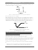
Move W2 on J5 to the cutback enable position (towards the bottom of the board).
Remove the input video signal and verify that the transmitter output drops to 25%.
Adjust R71, the cutback level, if necessary. Restore the input video.
Note: The following step affects the response of the entire transmitter.
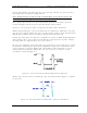
Connect a video sweep signal to the input of the transmitter. Monitor the output of the
system with a spectrum analyzer. Adjust C71 with R103 and C72 with R106, as needed,
to flatten the response. C71 and C72 adjust for the frequency of the correction notch
being applied to the visual response of the transmitter. R103 and R106 are used to
adjust the depth and width of the correction notch.
Refer to the alignment procedures for the setup of the linearity correctors. Controls
R13, R18, and R23, the magnitude controls, should be set fully CW. Controls R34, R37,
and R40 are the linearity cut-in adjustments.
4.1.8 (A11-A1) UHF Upconverter Board (1227-1237; Appendix B)
This board is mounted in (A11) a UHF upconverter enclosure assembly (1227-1238).
R10 is a gain control that is adjusted to give an approximately +17-dBm output at J5 of
the board.
4.1.9 (A14-A1) Channel Oscillator Board (1145-1201; Appendix B)
This board is mounted in (A14) the channel oscillator assembly (1145-1202).
To align this board, begin by connecting the main output of the channel oscillator, J1, to
a spectrum analyzer, tuned to the crystal frequency, and peak the tuning capacitors C6
and C18 for maximum output. Tune L2 and L4 for maximum output. The output level
should be about +5 dBm. The channel oscillator should maintain an oven temperature of
50
°
C.