
Data Sheet Chapter 4

3-kW UHF Transmitter Chapter 4, Detailed Alignment Procedures
835-3, Rev. 0 4-6
matching the level of the generator to the exciter. R17 adjusts the composite audio
gain.
Check the distortion level on the distortion analyzer (S/B =< 0.5%).
4.1.5 (A8) ALC Board (1227-1207; Appendix B) (Part 1 of 2)
The following explains the meaning of each LED on (A8) the ALC Board when they are
illuminated:
•
DS1 - Indicates that an abnormally low IF signal level is present at IF input
connector J1
•
DS2 - Indicates that the ALC circuit is unable to maintain the signal level requested
by the ALC reference; this is usually due to excessive attenuation in the linearity or
the IF phase corrector signal path, or switch S1 is in the Manual Gain mode
•
DS3 - Indicates a video fault
•
DS4 - Indicates that a Mute command is present
To align the ALC board, preset the following controls in the UHF exciter tray:
•
ALC Board – To disable linearity correctors: jumper W1 on J4 to Disable mode
(towards the bottom of the board); for manual gain control: jumper W3 on J6 to
Manual mode (towards the top of the board); R87, the manual gain pot, adjusted to
mid-range
•
IF Phase Corrector Board – W2 on J9 in phase correction enable; W3 on J10 in
amplitude correction disable
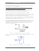
The combined IF output of the clamp modulator board is cabled to jack J1 of the ALC
board. Remove J1 from the board, and look to see that DS1, the Input Fault LED, is
illuminated. Reconnect J1 and check to see that DS1 is extinguished.
Jumper W3 on J6 should be in the Manual position (towards the top of the board).
Monitor jack J3, IF output, with a spectrum analyzer and adjust R87 for approximately a
–20-dBm level.
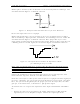
With a multiburst video signal present, tune C4 for a flat-frequency response of
±0.5 dB.
Before proceeding with the second part of the ALC board alignment, check the IF phase
corrector board to make sure that it is functioning properly.
4.1.6 (A9) IF Phase Corrector Board (1227-1250; Appendix B)
Refer to the alignment procedure for the setup of the IF phase corrector board.
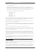
The IF input jack of the IF phase corrector board is fed from J3, the IF output jack of
(A8) the ALC board. The IF output jack is fed to J7, the IF input jack of the ALC board.
4.1.7 (A8) ALC Board (1227-1207; Appendix B) (Part 2 of 2)