
Data Sheet Chapter 4

3-kW UHF Transmitter Chapter 4, Detailed Alignment Procedures
835-3, Rev. 0 4-5
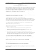
spectrum analyzer set at 1 dB/division. Tune R153 and C77, the IF frequency response
adjustments, for a flat-frequency response (±0.5 dB).
While still monitoring J20 with a spectrum analyzer, re-adjust R150, visual IF gain, for a
0-dbm visual output level. Adjust R127, A/V ratio, for a –13-dB aural-to-visual ratio or
to the required A/V ratio. Reconnect the plug to J20.
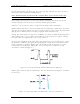
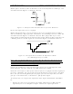
Using an input video test signal (the 5-step staircase) with 100-IRE white level, monitor
TP5 or video sample jack J7, pin 2, with an oscilloscope. Set control R31, the sync clip,
just below the point where sync clipping begins to occur. Similarly, set R28, the white
clip, to the point just below where the white video begins to clip.
Note: This procedure should be checked after system setup or if linearity problems
occur.
4.1.4 (A4) Aural IF Synthesizer Board (1227-1205; Appendix B)
To set up the test equipment for this board, begin by connecting the 600-ohm balanced
audio output from an audio oscillator to the balanced audio input jack of the transmitter,
J4-2 (+), J4-3 (-), and J4-1 (ground), on the A/V input and remote interface assembly
of the transmitter.
Connect the aural IF output at J16 on the clamp modulator board to the input of an IF
splitter. Connect one output of the splitter to the video demodulator and the other
output to the spectrum analyzer.
Connect a short cable at the front of the demodulator from the RF out jack to the IF in
jack.
Connect a cable from the 600-ohm audio output jack of the demodulator to the input of
an audio distortion analyzer.
Set the output frequency of the audio oscillator to 400 Hz and the output level to +10
dBm.
Center the aural carrier on the spectrum analyzer with the spectrum analyzer set to the
following:
Frequency/Division – 10 kHz
Resolution bandwidth – 3 kHz
Time/Division – 50 msec
Trigger – Free run
Adjust L5 for approximately +3.5 VDC on the cathode of CR17. The green LED DS1
should be illuminated, indicating a locked condition. If not, re-tune L5 for a locked
condition.
Adjust R13 on the aural IF synthesizer board for ±25-kHz deviation.
Check the distortion on the aural distortion analyzer (S/B =< 0.5%).
Disconnect the 600-ohm balanced audio input to the tray. Connect a 75-ohm stereo
audio input (400 Hz at 1 Vpk-pk) to composite audio input jack J6 on the A/V input and
interface assembly. Follow the procedure in the stereo generator instruction manual for