
Data Sheet Chapter 4

3-kW UHF Transmitter Chapter 4, Detailed Alignment Procedures
835-3, Rev. 0 4-4
splitter/coupler to the RF input of a television demodulator. Connect the direct port
to a spectrum analyzer.
•
Connect the 75-ohm video output of the demodulator to the video input of a
waveform monitor. For ICPM measurements, also connect the quadrature output of
the demodulator to the horizontal input of the waveform monitor using a 250-kHz
low pass filter (an oscilloscope can be used in place of a waveform monitor).
•
Set the controls of the demodulator to the following:
Detector mode – Cont
Sound Trap – In
Zero Carrier – On
Auto – Sync
Audio Source – Split
De-emphasis – In
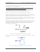
Move jumper W5 on J11 to the clamp disable position. Re-adjust pot R105, manual bias,
for the correct depth of modulation by observing the demodulated waveform on the
waveform monitor or on the spectrum analyzer set to zero span.
Move jumper W5 on J11 to the clamp enable position. Re-adjust pot R95, the clamp
bias, for the correct depth of modulation.
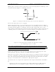
Set the waveform monitor to display ICPM. Preset R143 fully clockwise (CW) and adjust
C65 for the greatest effect at white on the ICPM display. Adjust R143 for minimum
ICPM.
Recheck the depth of modulation and adjust R95, clamp bias, if necessary.
Remove the video input signal. Alternately, turn the front panel meter switch between
the video and sync positions and adjust blanking pot R49 for a reading of zero on both
positions on the front panel meter.
Replace the input video test signal (the 5-step staircase). While monitoring the front
panel meter in the sync position, adjust R19 on the transmitter control board (1227-
1209) for a reading of 40 (4 on the 0 to 10 scale). Turn the front panel meter to the
video position and adjust R20 on the transmitter control board for a reading of 100 (10
on the 0 to 10 scale).
Place jumper W2 on jack J4 to the AGC enable position. Adjust R60, the sync level, for
the proper depth of modulation in the AGC mode. Return jumper W2 on jack J4 to the
AGC disable position.
Note: Use the AGC mode only if the incoming program video level cannot be
properly maintained.
Reconnect the plug to J18 and move the spectrum analyzer test cable to 41.25 IF output
jack J16. Tune C56 and L10 to L13 to maximize the 41.25-MHz aural IF signal and
minimize the out-of-band products.
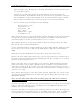
Reconnect the plug to J16 and move the spectrum analyzer test cable to IF output jack
J20. Preset R150, the visual IF gain pot, to the middle of the range. Insert a multiburst
test signal into the transmitter and observe the visual frequency response with the