
Data Sheet Chapter 4

3-kW UHF Transmitter Chapter 4, Detailed Alignment Procedures
835-3, Rev. 0 4-3
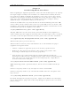
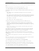
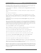
Monitor pin 13 of IC U6 (or TP7 on Revision 1 or later boards) with an oscilloscope. The
waveform shown in Figure 4-3 should be observed.
Figure 4-3. Waveform Observed When Pin 13 of IC U6 is Monitored
Restore the input video level to 1 Vpk-pk.
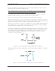
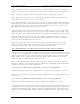
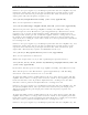
Monitor TP5 (on Revision 1 or later boards) or pin 2 of J7 (terminated into 75 ohms)
with an oscilloscope. Adjust pot R105, manual bias, for a blanking level of -0.8 VDC. The
waveform shown in Figure 4-4 should be observed. Move jumper W5 on J11 to the
clamp enable position (towards the bottom of the board). Adjust pot R95, clamp bias, for
a blanking level of -0.8 VDC. Again, the waveform in Figure 4-4 should be observed.
Figure 4-4. Waveform Observed When An Adjustment is Made
for a Blanking Level of –0.8 VDC
Note: The waveform in Figure 4-4 represents the theoretical level for proper
modulation depth. The second step below explains how to set the modulation
depth by the use of a television demodulator or a zero-spanned spectrum
analyzer tuned to the visual IF frequency.
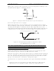
Connect the oscilloscope to the lead of L4 that is closest to C32 and adjust the color
notch subcarrier trap, C32, until the 3.58-MHz color burst is nulled.
Check the ratio of sync to video (0.286 volts of sync for a 1 Vpk-pk total video signal). If
necessary, adjust R43, the sync stretch cut-in (on Revision 6 or later boards, also adjust
R176, the sync stretch magnitude) for the proper sync ratio. Re-adjust R15, the video
gain pot, as described above, to maintain a 1 Vpk-pk video signal.
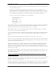
To construct the test setup for the adjustment of the depth of modulation and ICPM at
IF:
•
Remove the cable on J18 and connect the double sideband 45.75-MHz visual IF
signal from J18 to a 10-dB splitter/coupler. Connect the coupled port of the