
Data Sheet Chapter 4

3-kW UHF Transmitter Chapter 4, Detailed Alignment Procedures
835-3, Rev. 0 4-2
Set the controls R28, the white clip; R31, the sync clip; and R43, the sync stretch, to
their fully counter-clockwise (CCW) position.
Note: On Revision 6 or later boards, controls R43, sync stretch cut-in, and
R176, sync stretch magnitude, should be set fully CCW.
Place jumper W5 on jack J11 to the clamp disable position (towards the top of the
board) and jumper W2 on jack J4 to the AGC disable (out) position.
Connect a 5-step staircase video test signal to the input of the transmitter.
Monitor TP5 (on Revision 1 or later boards) with an oscilloscope. Adjust R15, the video
gain pot, for 1 Vpk-pk. Alternately, pin 2 on video sample jack J7 can be monitored for 1
Vpk-pk when terminated into 75 ohms (2 Vpk-pk when unterminated).
Change the video input test signal to a multiburst test pattern. While monitoring TP5 or
video sample jack J7, pin 2, adjust C8 and R35 for a flat-frequency response. Change
the input video test signal back to the 5-step staircase.
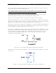
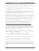
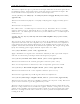
Decrease the amplitude of the input video test signal (the 5-step staircase) to 0.5 Vpk-
pk. (Double terminating the input will accomplish the required level reduction or R15
can be adjusted as needed.) Monitor pin 2 of IC U8B (or TP6 on Revision 1 or later
boards) with an oscilloscope. Adjust R76, the sync separator, to obtain a steady
waveform as shown in Figure 4-1.
Figure 4-1. Steady Waveform Obtained When R76 is Adjusted
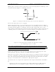
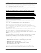
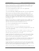
Monitor pin 9 of IC U9 with an oscilloscope. The waveform shown in Figure 4-2 should
be observed.
Figure 4-2. Waveform Observed When Pin 9 of IC U9 is Monitored