
Data Sheet Chapter 4

3-kW UHF Transmitter Chapter 4, Detailed Alignment Procedures
835-3, Rev. 0 4-10
Connect a sweep test signal to J1, the RF input jack of the 600-watt amplifier tray and
monitor the output of the board at J2 with a padded-input spectrum analyzer. Tune
capacitors C104 and C204 for peak output and then tune C106 and C206 for peak
output power with a flat-frequency response at J2.
4.2.5 (A4-A2) Coupler Board Assembly (1227-1316; Appendix B)
There are no adjustments to this board.
4.2.6 (A4-A3) Dual Stage Amplifier Board, Class AB (1227-1301; Appendix B)
This board is part of the dual stage amplifier assembly, class AB (1227-1339).
This board operates class AB and has a gain of approximately 9 dB. The biases of the
transistors are set by the on-board biasing circuits. Adjust R106 and R206 for 100
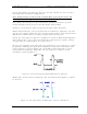
milliamps of idle current per side, no RF drive applied. Connect a voltage meter across
E1 and E2 on the amplifier protection board. Move switch S1 to the I4 position and
adjust R106 for a reading of 1.0 mV. Move switch S1 to the I3 position and adjust R206
for a reading of 1.0 mV.
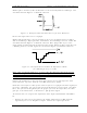
Connect a sweep test signal to J1, the RF input jack of the 600-watt amplifier tray, and
monitor the output of the board at J2 with a padded-input spectrum analyzer. Tune
capacitors C104 and C204 for peak output and then tune C106 and C206 for peak
output with a flat-frequency response and minimum current at J2.
4.2.7 (A5-A1) 4-Way Splitter Board (1227-1312; Appendix B)
There are no adjustments to this board.
Monitor the output of the tray at J2 with a padded-input spectrum analyzer.
4.2.8 (A5-A2, A5-A3, A5-A4, and A5-A5) Dual Stage Amplifier Boards, Class AB
(1227-1301; Appendix B)
Each of these boards is part of a dual stage amplifier assembly, class AB (1227-1339).
These boards operate class AB and have a gain of approximately 9 dB. The idling
currents for each of the transistors are set to 250 mA.
To adjust the idling currents, no RF applied to the tray, of the devices on the (A5-A2)
amplifier board, connect a voltage meter across E1 and E2 on the amplifier protection
board and switch S1 to the I6 position. Adjust R106 for a reading of 2.5 mV. Move
switch S1 to the I5 position and adjust R206 for a reading of 2.5 mV.
Connect a sweep test signal to J1, the RF input jack of the 600-watt amplifier tray. On
the (A5-A2) amplifier board, tune capacitors C104 and C204 for peak output power.
Tune C106 and C206 for peak output power with a flat-frequency response and
minimum current.
To adjust the idling currents, no RF applied to the tray, of the devices on the (A5-A3)
amplifier board, connect a voltage meter across E1 and E2 on the amplifier protection
board. Move switch S1 to the I8 position and adjust R106 for a reading of 2.5 mV. Move
switch S1 to the I7 position and adjust R206 for a reading of 2.5 mV.
Connect a sweep test signal to J1, the RF input jack of the 600-watt amplifier tray. On