
Data Sheet Chapter 4

3-kW UHF Transmitter Chapter 4, Detailed Alignment Procedures
835-3, Rev. 0 4-1
Chapter 4
Detailed Alignment Procedures
Before beginning the alignment procedures, make sure that the RF output at J2 of (A11)
the output coupler assembly of the transmitter is terminated into a dummy load of at
least 3000 watts. While performing the alignment, refer to the test data sheet for the
transmitter and compare the final readings from the factory with the readings on each
of the trays. The readings should be very similar. If one of the readings is off by a
significant degree, the problem is likely to be in that tray.
Switch on the UHF exciter tray circuit breaker on the AC distribution panel in the UHF
exciter cabinet and the circuit breaker on the rear of the UHF exciter tray for the 3-kW
transmitter. Also switch on the main and the individual amplifier circuit breakers on the
AC distribution panel in the amplifier array cabinet.
4.1 (A1) UHF Exciter Tray (1227-1200; Appendix A)
The (A1) UHF exciter tray has been factory tuned and should need no alignment to
achieve normal operation. Apply the baseband video and audio inputs of the test signals,
as needed, to the A/V input and remote interface panel on the rear of the transmitter.
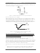
4.1.1 (Optional) (A6) Delay Equalizer Board (1227-1204; Appendix B)
This board may not be present in the tray.
This board has been factory tuned and should not be re-tuned without the proper
equipment. To align this board:
•
Connect a sinX/X test signal into jack J1-2 on the delay equalizer board.
•
Monitor the video output of the board at video sample jack J2 with a video
measuring set VM700 adjusted to measure group delay.
•
Tune the four stages of the board using the variable inductors (L1-L4) and
potentiometers (R7, R12, R17, and R22) until the signal attains the FCC group delay
curve. The stages are arranged in order of increasing frequency. Adjust R29, if
needed, for the desired video gain.
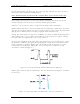
4.1.2 (A7) IF Carrier Oven Oscillator Board (1191-1404; Appendix B)
While monitoring J3 with a spectrum analyzer, observe the 45.75 MHz visual IF (+5
dBm).
Connect a frequency counter to J3 and adjust C17 for 45.750000 MHz.
Connect a frequency counter to J1 and check for 50 kHz; this is the aural phase lock
loop reference.
4.1.3 (A5) Clamp/Modulator Board (1227-1208; Appendix B)
Determine if jumper W1 on jack J3 is present. Jumper W1 terminates the video input
into 75 ohms. Remove jumper W1 if video loop-through is required on the rear chassis
jacks J1 and J2.