
System Description Chapter 2

500-Watt VHF Transmitter Chapter 2, System Description
425A, Rev. 0 2-9
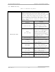
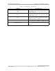
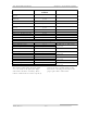
FUNCTION REMOTE JACK/PIN
NUMBER
INTERFACE TYPE
Auto/Manual Indicator
Return
J9-19
Transmitter Manual
Indicator
J9-20
50 mA max current sink
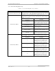
VSWR Cutback Indicator
J9-23
50 mA max current sink
VSWR Cutback Indicator
Return
J9-24
Video Loss (Fault) Indicator J9-25 50 mA max current sink
Video Loss (Fault) Ind. Rtn. J9-26
Receiver Fault (Optional) J9-30
Remote Metering
Visual Output Power J9-1
Visual Output Power Rtn J9-2
1V full scale at 1kΩ source
resistance
Aural Output Power J9-3
Aural Output Power Rtn J9-4
1V full scale at 1kΩ source
resistance
Reflected Power J9-5
Reflected Power Rtn J9-6
1V full scale at 1kΩ source
resistance
Exciter Output Power J9-7
Exciter Output Power Rtn J9-8
1V full scale at 1kΩ source
resistance
The remote connections shown in Table
2-11 are made to the (A12) A/V input
and remote interface assembly. These
remote connections are made to jacks J9
and J10 on the assembly. Refer to the
interconnect drawing (1076203) for the
proper pin remote connections.