
System Description Chapter 2

500-Watt VHF Transmitter Chapter 2, System Description
425A, Rev. 0 2-7
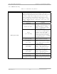
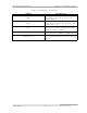
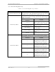
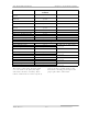
Table 2-7. 600-Watt Amplifier Tray Fault Indicators
INDICATOR DESCRIPTION
Overdrive (DS1)
Indicates that the level of drive is too high.
The protection circuit will limit the drive
level to the set threshold. The fault is
generated on the overdrive protection
board.
Enable (DS2)
Indicates that the Enable supplied by the
exciter tray is present
Module Status (DS3)
Indicates that the forward power sample
level is lower than the set reference level
VSWR Cutback (DS4)
Indicates that the reflected level of the
tray has increased above 20%; this will
automatically cut back the output power of
the tray. The fault is generated on the
AGC control board.
Overtemp (DS5)
Indicates that the temperature of (A4-A5,
A4-A6 or A5-A2) the thermal switch is
above 80° C. When this fault occurs, the
Enable to the switching power supply is
immediately removed.
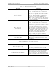
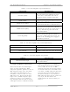
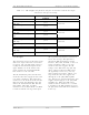
Table 2-8. 600-Watt Amplifier Tray Control Adjustments
ADJUSTMENT DESCRIPTION
Phase (A7-R2)
Adjusts the phase of the RF output by
approximately 70%
Gain (A6-R3)
Adjusts the gain of the RF output when the
amplifier control board is in the AGC mode
Table 2-9. 600-Watt Amplifier Tray Sample
SAMPLE DESCRIPTION
RF Front Panel Sample
Forward power sample of the tray from the
AGC control board
2.3 Input and Remote Connections
The baseband video and audio inputs
alone or, if the (optional) 4.5-MHz
composite input kit is purchased, the 4.5-
MHz composite input or the baseband
video input and audio input to the
transmitter, connect to the rear of the
VHF exciter tray. The baseband video
input or the 4.5-MHz composite input
connects to jacks J1 or J2, which are
loop-through connected. The baseband
audio input connects to TB1 for balanced
audio or to jacks J3 or J13, which are
loop-through connected, for composite,
stereo, audio. To use the 4.5-MHz
composite input kit, the baseband audio
can remain connected to the VHF exciter
even if the 4.5-MHz composite input kit is
used, but the baseband video must be
disconnected from J1 or J2 and the 4.5-
MHz composite input must be connected
to J1 or J2. The baseband select
command must be removed from J7-6
and J7-7.