
Manual Chapter 3


500-Watt UHF Transmitter Chapter 3, Circuit Descriptions
425A, Rev. 0 3-28
thermal fault occurs, the AGC control
board will not enable the switching power
supply. As a result, the +48 VDC will be
removed from the amplifier modules and
the front panel Enable and Module Status
LEDs will not be lit.
The front panel meter (A9) uses the front
panel Selector switch S1 to monitor the
AGC Voltage, % Output Reflected Power,
% Forward Power, and the Switching
Power Supply Voltage (+48 VDC). The
meter in the AGC position will read
anywhere from .5 volts to 3 volts. The
meter is calibrated in the Power Supply
position using R86 on the AGC control
board. The % Output Power is calibrated
using R44 and the % Reflected Power is
calibrated using R53 on the AGC control
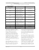
board. With S1 in the Current position,
S2 can be switched to read the idling
currents, no RF drive applied, of the
high-band amplifier boards. Typical
readings are an idling current of 2 amps
visual, or visual + aural, or 1 amp aural
in the amplifier assembly I
1
, I
2
, I
3
, and I
4
positions.
The reflected power sample from the 4-
way combiner board is fed back to the
AGC control board at J5. On the board,
the reflected sample is connected
through the detector circuit to VSWR
cutback circuit U13C. If the reflected
power increases above 20%, the output
power of the tray, as set by R60 (the
VSWR cutback on the AGC control
board), will be cut back to maintain a
20% reflected output level.
The red VSWR Cutback LED DS4 on the
front panel will remain lit until the
reflected level drops below 20%.
There are three thermal switches in the
tray for overtemperature protection. Two
of the thermal switches (A4-A5 and A4-
A6) are mounted on the rear of (A4) the
heatsink for the high-band amplifier
boards and the third thermal switch (A5-
A2) is mounted on the heatsink for (A5-
A1) the 4-way combiner board. The
thermal switches close when the heatsink
on which they are mounted reach a
temperature of 175° F. The closed
thermal switch causes the AGC control
board to remove the enable to the
switching power supply. This eliminates
the +48 VDC and lights the red
Overtemperature LED DS5 on the front
panel. The AGC control board will
extinguish the Module Status LED DS3.
3.3 (A9) Bandpass Filter Assembly
(1067297; Appendix C)
The RF input connects to the (A9)
constant impedance bandpass filter
assembly (1067318) at jack J1 of (A1) a
splitter/combiner board (1092-1092).
The splitter/combiner board divides the
combined RF signal into two signals
before feeding it to jack J1 of (A2 and
A3) two 5-section bandpass filters with
traps. These filters screen the 6 MHz-
wide signal and attenuate the –4.5-MHz
and +9-MHz out-of-band products. These
signals connect to jacks J2 and J3 on
(A4) the other splitter/combiner board
(1092-1092), that recombines the two
signals before sending them on to jack J1
of (A5) the directional coupler module
(1092-1308). The directional coupler
module provides forward and reflected
samples to the exciter tray for metering
purposes.