
Manual Chapter 3


500-Watt UHF Transmitter Chapter 3, Circuit Descriptions
425A, Rev. 0 3-27
cutback protection if the reflected power
level increases above the preset level.
Two voltages, +48 VDC from the internal
switching power supply and +12 VDC
from the exciter control panel, are
needed for the operation of the tray. The
+12 VDC connects to J3-7 and J3-8 on
the rear of the tray; these are wired to
J8, pins 4 and 1, on (A13) the AGC
control board. The +12 VDC is connected
to U8, a +5 VDC regulator IC that
supplies the +5 VDC needed for the
operation of the front panel-mounted
LEDs.
The (A10) +48 VDC switching power
supply provides the +48 VDC to (A8) the
current metering board (1198-1609). The
current metering board distributes the
voltages through fuses to the amplifier
devices on the filter/amplifier, the high-
band driver board, the high-band
amplifier board, and the four final high-
band amplifier boards. The fuses F1, F2,
F3, and F4 are 10-amp fuses; F5 is a 5-
amp fuse; and F6 and F7 are 1-amp
fuses. There are two spare fuses, one 1
amp and one 10 amp, on the top, right-
hand side of the tray. Fuse F1 protects
(A4-A1) the high-band amplifier board;
fuse F2 protects (A4-A2) the high-band
amplifier board; fuse F3 protects (A4-A3)
the high-band amplifier board; fuse F4
protects (A4-A4) the high-band amplifier
board; fuse F5 protects (A3-A2) the high-
band amplifier board; and fuse F6
protects (A2-A1) the filter/amplifier
board. Fuse F7 supplies +48 VDC to J8,
pin 2, on the AGC control board. The +48
VDC is connected to regulator IC U7 that
takes the +48 VDC and provides a +12
VDC output. The +12 VDC is used for the
operation of the AGC control board. The
+12 VDC is also connected through the
current metering board, jumpered from
TB1-5 to TB1-6, to the phase shifter
board, the filter/amplifier board, and the
overdrive protection board.
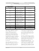
The current metering board also supplies
sample outputs of the operating currents
of the amplifier devices in the tray to the
front panel current meter. The meter in
the (I
1
) position reads the current for the
(A4-A1) high-band amplifier board; the
meter in the (I
2
) position reads the
current for (A4-A2) the high-band
amplifier board; the meter in the (I
3
)
position reads the current for the (A4-A3)
high-band amplifier board; and the meter
in the (I
4
) position reads the current for
the (A4-A4) high-band amplifier board.
To read the desired current, place switch
S2 in the proper position, checking that
S1 is in the Current position. These
current readings can be used when
setting up the idling currents, no RF drive
applied, for the devices. (I
1
, I
2
, I
3
, and I
4
)
are each set for 2 amps when the tray is
a visual amplifier, or a visual + aural
amplifier, and they are set for 1 amp
when the tray is an aural amplifier.
230 VAC is applied through jack J4 to
terminal block TB1 in the tray. When
CB1, the 15-amp, front panel-mounted
circuit breaker, is switched on, the 230
VAC is distributed from TB1 to (A11 and
A12) two cooling fans, which will begin to
operate, and to (A10) the switching
power supply. There are two surge
suppressors, VR1 and VR2, mounted on
TB1 that provide protection from
transients or surges on the input AC line.
There are two other surge suppressors,
VR3 and VR4, mounted at the input to
the switching power supply from each AC
line to ground, that provide protection
from transients or surges on the AC line.
The switching power supply only
operates when the power supply enable
control line, jack J3, pins 9 and 10, on
the rear of the tray, is shorted. The
enable is generated by the control panel
when the amplifier array is switched to
Operate. The enable is applied to (A13)
the AGC control board (1142-1601)
which, if there is no thermal fault,
connects the enable from J10, pins 6 and
7, to J1-6 and J1-8 on the switching
power supply assembly. The green
Enable LED DS2 on the front panel will
light, indicating that an enable is present.
If the amplifier array is in Standby, or if a