
Manual Chapter 3


500-Watt UHF Transmitter Chapter 3, Circuit Descriptions
425A, Rev. 0 3-24
The gate of Q1 is connected to pin 13 on
U4, which is the maximum count used in
the EEPROM, and will provide a reset
pulse each time the binary counter goes
high on pin 13. The reset pulse, when the
drain of Q1 goes low, is applied to the
flip-flop and the timer U3, which
determines the length of time between
the sending of the identification code.
R14 is adjusted to set this time interval.
R14, fully CW, is the longest interval
between identification calls,
approximately eight minutes. R14, fully
CCW, is the shortest interval between the
sending of the code (approximately 10
seconds).
U6B is an amplifier connected to the
output of U5, which turns the LED DS1
on and off at the rate set by R2. This
gives the operator a visual indication that
the FSK identifier board is operating and
at the rate at which it is operating.
The data output of U5, which is serial, is
connected to U6A, whose output shifts
low and high, and is applied to the VCXO
board, which shifts the frequency
according to the programming of U5. The
deviation of the shift is adjusted by R4
and is typically set at 1 kHz. Once R4 is
set, R9 is re-adjusted to -1.5 VDC at J3-
2.
The +12 VDC from an external power
supply enters the board at J1, pin 3. The
voltage is fed through RF choke L1 and is
filtered by C1 before being applied to the
rest of the tray. The +12 VDC is also
applied to U7, which is a voltage
regulator that regulates its output at +5
VDC. The +5 VDC is fed to the ICs on the
board. The -12 VDC from an external
power supply enters the board at J1, pin
5. The voltage is fed through RF choke L2
and filtered by C2 before being applied to
the rest of the tray.
3.1.12 (A4-A12) IF Attenuator Board
(1150-1201; Appendix D)
The IF attenuator board is operated with
the FSK identifier board to produce an
amplitude-modulated aural IF signal for
broadcasting the required FCC station
identification call sign at the proper time
intervals.
The board contains a pin-diode
attenuation circuit that consists of CR1
and the two resistors R2 and R3. The
bias output of the FSK identifier board is
applied to J3 of the IF attenuator board.
As the bias applied to J3 increases and
decreases, the amplitude of the aural IF
signal, which enters the board at J1 and
exits the board at J2, will increase and
decrease. This produces an amplitude-
modulated IF signal at J2, the aural IF
output jack of the board.
3.2 (A6 and A7) 600-Watt High-Band
VHF Amplifier Trays (1219-1100;
Appendix C)
The 600-watt high-band VHF amplifier
tray (1219-1100) can be adjusted at the
factory for use as either a visual, a visual
+ aural, or an aural RF amplifier tray. As
a visual amplifier, the tray has
approximately 55 dB of gain at the
frequency of the VHF high-band channel
and will take the typical +3 dBm input
and amplify it to an output level of
approximately +58 dBm, 100%=600
watts peak of sync. As an aural amplifier,
the tray is calibrated for 400 watts equals
100% output. As a visual + aural
amplifier, the tray is calibrated for 300
watts peak of sync visual plus –10 dB or
–13 dB aural power (30 watts or 15
watts).
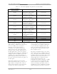
The tray is made up of the boards and
assemblies listed in Table 3-1.