
Manual Chapter 3


500-Watt UHF Transmitter Chapter 3, Circuit Descriptions
425A, Rev. 0 3-21
the drain to go low. The low is connected
to J8-12, which can light any remote
receiver fault indicator that is connected
to it.
3.1.8.9 Metering
The front panel meter connects to J3-1
(-) and J3-2 (+), the output of switch S3,
on the transmitter control board. The
front panel meter has seven metering
positions which are controlled by S3:
Audio, Video, % Aural Power, % Visual
Power, % Reflected Power,
% Exciter, and ALC. The video sample
connects to the board at J5-4 and is
connected through video calibration pot
R20 to position 6 on front panel meter
switch S3. The audio sample enters the
board at J5-6 and is connected through
audio calibration pot R19 to position 7 on
front panel meter switch S3.
The reflected sample connects to the
board at J2-9 and is connected through
buffer amplifier U1B and 100Ω resistor
R84 to position 3 on front panel meter
switch S3. The visual sample connects to
the board at J2-5 and is connected
through buffer amplifier U1D and 100Ω
resistor R86 to position 4 on front panel
meter switch S3. The aural sample
connects to the board at J2-7 and is
connected through buffer amplifier U1C
and 100-watt resistor R85 to position 5
on front panel meter switch S3. The
exciter sample connects to the board at
J2-3 and is connected through buffer
amplifier U1A and 100Ω resistor R87 to
position 2 on front panel meter switch
S3. The ALC sample connects to the
board at J6-1 and is connected through
buffer amplifier U2C and ALC calibration
pot R15 (which adjusts the output of
U2A, pin 1) and through 100Ω resistor
R18 to position 1 on front panel meter
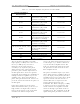
switch S3. Typical readings on the meter
are:
• Video = 1 Vpk-pk at white
• % Reflected = < 5%
• % Visual power = 100%
• % Aural power = 100%
• % Exciter = The level on the meter
needed to attain 100% output power
from the transmitter
Refer to the test specifications sheet for
the transmitter for the actual reading:
• ALC = .8 VDC
• Audio = ±25 kHz with a balanced
audio input or ±75 kHz with a
composite audio input
Samples are provided for the remote
metering of the exciter at J1-10, the
visual at J8-26, the aural at J8-27, and
the reflected at J1-5.
U6 is a temperature-sensor IC that gives
the operator the ability to measure the
temperature inside the tray by measuring
the voltage at TP1. The sensor is set up
for +10 mV equals 1° F (for example,
750 mV equals 75° F).
3.1.8.10 Operational Voltages
The +12 VDC needed for the operation of
the transmitter control board enters the
board at jack J4, pin 3. C28, L1, and L3
are for the filtering and isolation of the
+12 VDC before it is split and applied to
the rest of the board. The -12 VDC
needed for the operation of the board
enters the board at jack J4, pin 5. C29
and L2 are for the filtering and isolation
of the -12 VDC before it is split and
applied to the rest of the board.
The +12 VDC is split when it is connected
to the board. Four of the +12 VDC
outputs are fed out of the board at J8-16,
J8-17, J8-18, and J8-19 through diodes
CR7, CR8, CR9, or CR10 and resistors
R50, R51, R52, or R53 are fed to any
external amplifier trays for use in their
logic circuits. The resistors are for current
limiting and the diodes are to prevent
voltage feedback from the external
amplifier trays.