
Installation Instructions Chapter 4

500-Watt VHF Transmitter Chapter 4, Installation and Setup Procedures
425A, Rev. 0 4-7
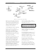
level is being checked, observe the meter
reading in the % Reflected Power
position. If the % Reflected Power is very
high, above 10%, a problem exists with
the output coaxial lines and they will
need to be checked. A center bullet
missing from the coax lines or loose bolts
on the connections can cause this
problem. Return the Operate/Standby
switch to Standby.
The gain and phase controls on the front
panels of the individual VHF amplifier
trays were adjusted at the factory to
obtain an output of 100% for the
transmitter and should not need to be
readjusted.
The front panel readings on the individual
VHF amplifier trays may not be the same.
Refer to the Test Data Sheet for the
transmitter to compare the final readings
from the factory with the readings on
each of the trays after the setup. They
should be very similar. If a reading is off
by a significant amount, refer to the
phasing and power adjustment
procedures for the VHF amplifier trays in
Chapter 5, Detailed Alignment
Procedures, of this manual before trying
to make any adjustments.
If a dummy load is connected to the
transmitter, switch the unit to Standby
and switch off the main AC circuit
breaker. Remove the dummy load and
make all of the connections that are
needed to connect the transmitter to the
antenna. Switch the main AC circuit
breaker on and the Operate/Standby
switch to Operate. Adjust the output
power screwdriver pot to achieve an
output of 100%.
If the transmitter is already connected to
the antenna, check that the output is
100%. If necessary, adjust the power
screwdriver pot.
This completes the transmitter setup and
operation procedures for the 425A VHF
solid-state transmitter. The transmitter
can now be operated normally.
If a problem occurred during the setup
and operation procedures, refer to
Chapter 5, Detailed Alignment
Procedures, of this manual for more
information.