
Installation Instructions Chapter 4

500-Watt VHF Transmitter Chapter 4, Installation and Setup Procedures
425A, Rev. 0 4-6
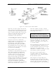
4.4 Setup and Operation
Initially, the transmitter should be turned
on with the RF output at (A9-A5-J2) the
coupler assembly terminated into a
dummy load of at least 500 watts. If a
load is not available, check that the
output of the coupler assembly is
connected to the antenna.
Connect the baseband balanced audio
input to the terminal block TB1 or the
composite audio input to BNC jack J3 or
J13 on the rear of the UHF exciter. The
baseband audio input can remain
connected when using the 4.5-MHz
composite input without affecting the
operation of the tray. Connect the
baseband video input to BNC jack J2 or
J1 also on the rear of the UHF exciter or,
if the (optional) 4.5-MHz composite input
kit is purchased, connect the 4.5-MHz
composite input to BNC jack J2 or J1. To
use the 4.5-MHz composite input, the
4.5-MHz composite input must be
connected to J2 or J1 and the baseband
select must be removed from J7-6 and
J7-7 on the rear of the tray. To use the
baseband video and audio inputs, the
baseband video input must be connected
to J2 or J1, the baseband audio must be
connected to the proper jack, and the
baseband select must be connected from
J7-6 and J7-7.
If the optional (A12) A/V input and
remote interface assembly is present in
the system, the baseband balanced audio
input connects to the terminal block TB1
or the composite audio input to BNC jack
J6. The baseband audio input can remain
connected when the 4.5-MHz composite
input is in use without affecting the
operation of the tray. Connect the
baseband video input to BNC jack J2 on
the A/V input and the remote interface
assembly or, if the (optional) 4.5-MHz
composite input kit is purchased, connect
the 4.5-MHz composite input to BNC jack
J2. To use the 4.5-MHz composite input,
the 4.5-MHz composite input must be
connected to J2 and the baseband select
must be removed from J7-6 and J7-7 on
the rear of the UHF exciter tray. To use
the baseband video and audio inputs, the
baseband video input must be connected
to J2, the baseband audio must be
connected to the proper jack, and the
baseband select must be connected from
J7-6 and J7-7 on the rear of the UHF
exciter tray.
Switch on the main AC, VHF exciter, and
the amplifier #1 and amplifier #2 circuit
breakers on the AC distribution panel
facing the rear of the cabinet and
mounted behind the rear door. On the
VHF exciter tray, switch the
Operate/Standby switch to Standby and
the Auto/Manual switch to Manual.
Normal operation of the transmitter is in
Automatic. Automatic operation uses the
video input to the UHF exciter as an
Operate/Standby switch. In Auto, if the
input video is lost for approximately 7
seconds, the transmitter will
automatically revert to Standby and,
when the video signal is restored, the
transmitter will quickly return to Operate.
Move the Operate/Standby switch on the
UHF exciter tray to Operate. Observe the
power supply reading, +48 V, on the
front panel of the VHF amplifier trays.
Note: If the transmitter does not
switch to Operate when the
Operate/Standby switch is placed in
Operate, check that an external
interlock plug, with a jumper wired
from pins 23 to 24, is connected to
jack J11 on the rear of the VHF
exciter. If (A12) the (optional) A/V
input and remote interface assembly
are present in the system, the
external interlock plug, with a
jumper wired from pins 21 to 22, is
connected to jack J9 on the
assembly.
On the VHF exciter tray, look at the front
panel meter reading in the % Visual
Power position; it should read 100%. If
necessary, readjust the screwdriver
adjust power pot on the front panel of
the VHF exciter for 100%. As the power